

We’ve been building manual and motorized stages for over 9 years. We also make automated alignment platforms. So we’ve seen a lot of EMI problems. Some are easy. Some make you want to pull your hair out.
If you work with optical alignment, you know the feeling. The stage moves. The camera looks. The image is noisy. The position is off by a few microns. You check the mechanics. Everything is tight. Then you realize the problem isn’t mechanical. It’s electrical noise.
This guide is for buyers, engineers, and anyone who needs a servo motor stage that actually works in a real factory. No fluff. Just practical stuff we’ve learned from real projects.
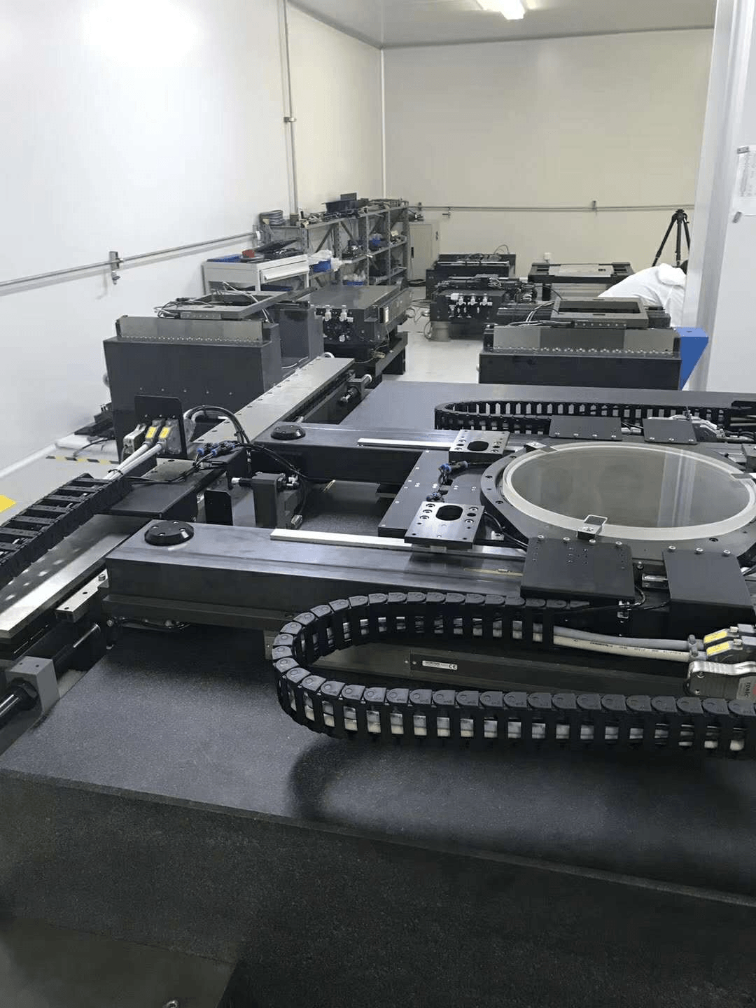
What EMI Does to a Servo Motor Stage
EMI stands for electromagnetic interference. It’s unwanted electrical noise. It can travel through cables or through the air. When it gets into your stage, it messes with the drive, encoder, camera, or sensors.
The result? Motion control interference. The stage doesn’t move exactly where you told it to. Sometimes it’s a tiny error. Sometimes it’s a big one. In optical alignment, even a tiny error is a big deal.
We’ve seen a standard stage with 2 µm repeatability in the lab. On the production line, it dropped to 15 µm. Same stage. Same mechanics. The only difference was EMI from nearby equipment.
Where EMI Comes From in Motorized Stages
EMI in motorized stages usually comes from four places. Let’s break them down.
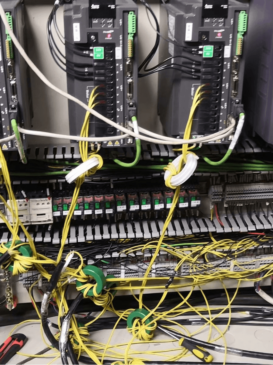
The Drive Is Usually the Main Suspect
Most servo drives use PWM. That means they switch power on and off very fast. We’re talking 10 kHz to 100 kHz or more. This fast switching creates high-frequency noise. It’s the biggest source of EMI in most systems.
Cables and Grounding: The Usual Suspects
Power cables and signal cables should never run together. If they do, noise jumps from one to the other. We’ve seen a 3-meter run of unshielded encoder cable next to a 220 V power cable. That added 10 µm of error. Just from cable routing.
Bad grounding is another big one. A ground loop acts like an antenna. It picks up noise and sends it straight to your encoder or camera.
Encoders and Cameras Are the Victims
Encoders send low-voltage signals. They’re easy to disturb. If the encoder cable isn’t shielded, noise can change the pulses. The drive then thinks the stage is somewhere it isn’t.
Cameras are also sensitive. EMI shows up as lines, snow, or rolling bars in the image. The software sees the wrong edge. It calculates the wrong offset. The stage moves to the wrong place.
Other Sources You Might Not Think About
Welders, pumps, lasers, and even fluorescent lights can create EMI. We once had a customer whose stage faulted every time a nearby welder turned on. The stage was fine. The environment was the problem.
Why Automated Optical Alignment Is So Sensitive
EMI in Motorized Stages for Automated Optical Alignment Platforms is a common and costly issue. Here’s why.
Optical alignment is a closed-loop process. The camera looks at a mark. Software calculates the offset. The stage moves to correct it. Then the camera checks again. If EMI enters the camera signal, the image is not clear. If EMI enters the encoder signal, the drive gets confused. The loop never settles.
In many factories, the target is 1 µm to 5 µm. EMI can easily add 10 µm to 50 µm of error. That’s the difference between passing and failing.
How to Reduce Motion Control Interference in Servo Motor Stages for Automated Optical Alignment Platforms?
This is the big question. How to Reduce Motion Control Interference in Servo Motor Stages for Automated Optical Alignment Platforms? The answer is not one magic part. It’s a system approach.
Here are 8 things we do in real projects.
1. Use Shielded Twisted-Pair Cables
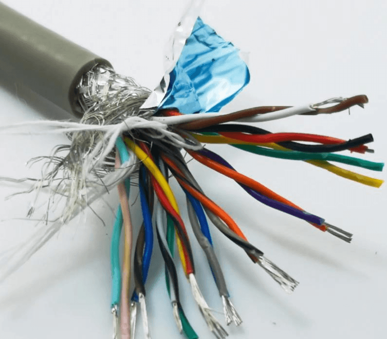
Shielding blocks electric fields. Twisting cancels magnetic fields. Use shielded twisted-pair for encoders. Use shielded cables for motor power. Connect the shield at both ends for high-frequency noise. For low-frequency noise, try one end. Test both.
A good shield can cut noise by 20 dB to 40 dB. That’s 10 to 100 times less noise voltage.
2. Keep Power and Signal Wires Apart
Keep power cables at least 20 cm away from signal cables. If they must cross, cross at 90 degrees. Never run them parallel for long distances. This simple rule can reduce motion control interference by half or more.
3. Fix Your Grounding
Use a single-point ground for analog signals. Use a ground plane for high-frequency noise. Keep ground wires short and thick. Avoid daisy chains. A bad ground can make EMI worse, not better.
4. Add EMI Filters and Ferrite Cores
Install an EMI filter on the AC input of the drive. Add ferrite cores on motor and encoder cables. A ferrite core can add 10 dB to 30 dB of impedance at high frequency. It stops noise from traveling along the cable.
5. Choose Low-EMI Drives and Motors
Not all drives are equal. Some have soft switching. Some have built-in filters. Some motors have better winding design. Ask for EMI test data. A low-EMI servo motor stage may cost 10% to 20% more. But it can save 50% of debugging time.
6. Improve Encoder Feedback
Use differential encoders instead of single-ended. Differential signals reject common-mode noise. Use optical encoders in strong magnetic fields. Use magnetic encoders in dirty environments. Match the encoder to the job.
7. Measure Before You Fix
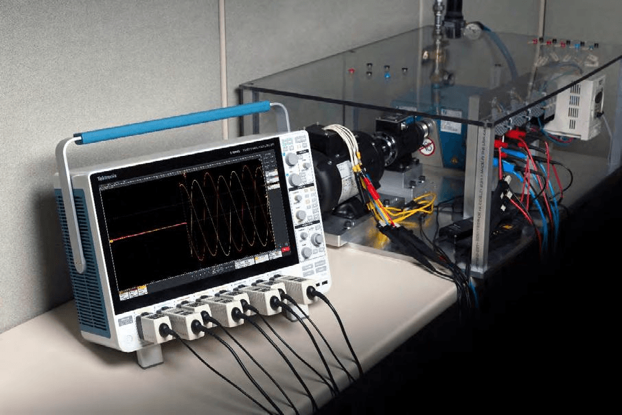
You can’t fix what you can’t measure. Use an oscilloscope to look at encoder signals. Use an EMI receiver to find radiated noise. Check near the camera, encoder, and drive. Record the noise level before and after each fix.
8. Use Software Filters as a Last Resort
Sometimes hardware isn’t enough. You can add a notch filter in the drive. You can add a low-pass filter in the camera software. You can average multiple readings. These methods don’t remove EMI, but they reduce its effect.
Table 1 shows what kind of improvement you can expect.
|
Method |
Typical Noise Reduction |
Cost |
Difficulty |
|
Shielded cables |
20–40 dB |
Low |
Easy |
|
Separate power/signal |
50% less crosstalk |
Low |
Easy |
|
Proper grounding |
10–30 dB |
Low |
Medium |
|
EMI filter |
20–40 dB |
Medium |
Medium |
|
Ferrite cores |
10–30 dB |
Low |
Easy |
|
Low-EMI drive |
10–20 dB |
High |
Easy |
|
Differential encoder |
20–40 dB |
Medium |
Medium |
|
Software filter |
6–20 dB |
Low |
Medium |
Low EMI Servo Motor Stage vs Standard Servo Motor Stage for Automated Optical Alignment
When you buy a stage, you have a choice. You can buy a standard stage. Or you can buy a low EMI stage. The Low EMI Servo Motor Stage vs Standard Servo Motor Stage for Automated Optical Alignment comparison is important. It affects price, lead time, and performance.
Here’s how they compare.
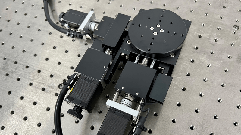
| Feature | Standard Servo Motor Stage | Low EMI Servo Motor Stage |
| Motor cable | Unshielded or basic shield | Double shielded |
| Encoder cable | Standard | Shielded twisted pair |
| Grounding | Basic | Star ground + ground plane |
| EMI filter | Not included | Built-in or recommended |
| Drive | Standard PWM | Low-noise PWM or filtered |
| Ferrite cores | Optional | Included |
| Encoder type | Single-ended or standard differential | Differential with high CMRR |
| Cable routing | User-defined | Pre-designed and tested |
| EMI test data | Not available | Available on request |
| Price | 100% | 110%–130% |
| Best for | General automation | Optical alignment, metrology, medical |
| Setup time | Longer | Shorter |
| Risk of interference | Higher | Lower |
A standard stage is fine for simple tasks. If you move from point A to point B with 50 µm accuracy, EMI may not matter. But if you align optical components with 1 µm accuracy, a standard stage may fail.
A low EMI stage costs more. But it reduces risk. It saves engineering time. It improves yield. In many projects, the extra cost pays back in weeks.
A Simple Selection Checklist
How do you choose the right servo motor stage? Use this checklist.
Step 1: Define your EMI environment. List nearby equipment. Welders, pumps, lasers, and drives are strong noise sources. Check the distance. Check the frequency.
Step 2: Check repeatability, not just resolution. A stage may have 0.1 µm resolution. But if repeatability is 5 µm, it can’t hold 1 µm alignment. Ask for test data under EMI.
Step 3: Ask about shielding and grounding. Are the cables shielded? How is the shield connected? Is there a ground plane? Can you provide a grounding diagram?
Step 4: Review cable and connector design. Metal connectors are better than plastic. They provide shielding. Check the cable bend radius. A tight bend can break the shield.
Step 5: Request EMI test data. Ask for radiated and conducted emissions data. Ask for immunity test data. If the supplier can’t provide it, be careful.
Step 6: Consider total cost. Don’t compare only the stage price. Include engineering time, debugging time, downtime, and yield loss.
Real Cases from Our Shop Floor
We’ve seen EMI in motorized stages in many industries. Here are four real cases.
Case 1: Semiconductor wafer inspection. A customer used a standard servo motor stage. The camera saw 5 µm noise. The stage repeatability was 3 µm. After adding shielded cables and a ferrite core, noise dropped to 1 µm. Yield improved by 8%.
Case 2: Display panel repair. A display repair system had random drive faults every 20–30 cycles. The cause was a ground loop between the stage and the laser. A single-point ground and an isolation transformer fixed it. Faults stopped completely.
Case 3: Medical slide scanning. A medical scanner needed smooth motion. The stage vibrated at 100 Hz. The cause was PWM noise from the drive. A low-pass filter and a low-EMI drive reduced vibration by 90%.
Case 4: Laser alignment. A laser alignment platform had 10 µm position error. The encoder cable was unshielded. It ran next to a 220 V power cable for 3 meters. After separating the cables and using a shielded encoder cable, error dropped to 1.5 µm.
FAQ
How to Reduce Motion Control Interference in Servo Motor Stages for Automated Optical Alignment Platforms?
Use shielded cables. Separate power and signal. Ground properly. Add filters and ferrites. Choose a low-EMI stage. Test with an oscilloscope. These steps reduce motion control interference by 80% to 95% in most cases.
What is the biggest source of EMI in a servo motor stage?
The PWM servo drive is the biggest source. Motor cables are second. Ground loops are third.
Can I fix EMI without changing the stage?
Yes. You can add filters, ferrites, and shielded cables. You can improve grounding. But if the stage design is poor, you may only get partial improvement.
How much does a low EMI servo motor stage cost?
A low EMI stage costs 10% to 30% more than a standard stage. The exact price depends on travel, load, and accuracy.
Do I need a low EMI stage for a cleanroom?
Cleanroom does not remove EMI. But cleanroom equipment is often sensitive. A low EMI stage is a good choice for cleanroom optical alignment.
How do I test EMI?
Use an oscilloscope for signal noise. Use an EMI receiver for radiated noise. Test at the camera, encoder, and drive. Compare before and after each fix.
Why Work With Us
We’ve been in this business for over 9 years. We make manual and motorized stages. We also make automated alignment platforms. We focus on R&D, production, and sales. We understand EMI because we test it every day.
Our servo motor stage options include:
Low EMI cable sets.
Shielded encoder cables.
Built-in EMI filters.
Differential encoders.
Custom grounding design.
EMI test data on request.
We don’t just sell a stage. We help you solve the whole motion problem. If you have an EMI issue, send us your setup. We can review your cables, grounding, and drive settings. We can recommend a low EMI stage that fits your budget.
Let’s Talk About Your EMI Problem
Are you building an automated optical alignment platform? Are you tired of motion control interference? Do you need a servo motor stage that works in a noisy factory?
Contact us today. Tell us your accuracy target, travel range, load, and environment. We’ll give you a clear recommendation. We’ll also share test data and selection advice. Let’s reduce EMI and improve your yield.
Email us now. Get a fast quote. Solve your EMI problem with a stage built for real production.
Post time: Oct-19-2026


