

Troubleshooting Linear Stage Wobble and Pitch Errors in Multi-Axis Systems
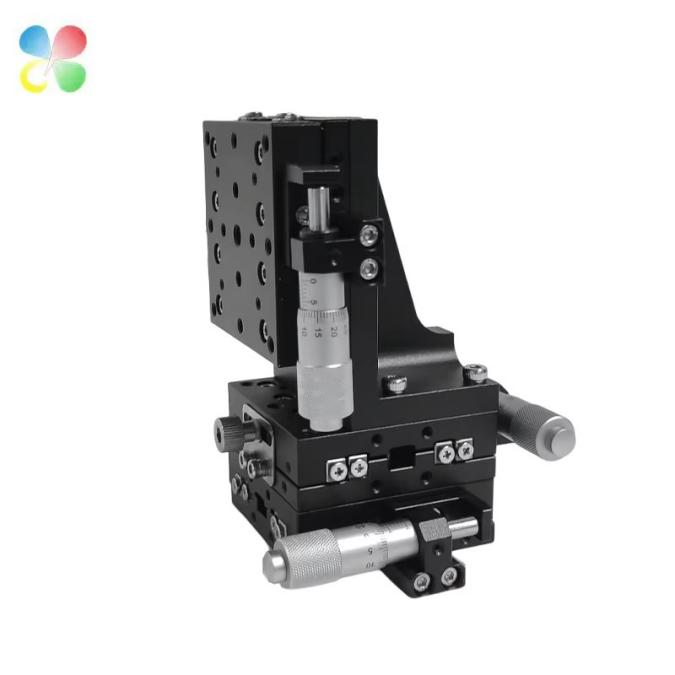
Have you ever set up a fresh multi-axis system, dialed in your vision camera, started your motion sequence — and watched the image drift out of focus for no apparent reason? Or maybe you’ve seen your laser micromachining cut quality shift across the work area even though the power and speed settings stayed the same. The culprit is often hiding in plain sight: tiny angular errors called wobble and pitch.
These errors feel sneaky. They don’t always trigger alarms. They slowly eat into your process margin until parts start failing inspection. As a precision stage manufacturer with over nine years on the factory floor, we’ve seen this story play out across hundreds of projects. Our goal here is to walk you through it — not with textbook theory, but with practical, boots-on-the-ground troubleshooting.
And we’ll tackle the question we get asked most often: “How can I effectively reduce linear stage wobble and troubleshoot pitch errors in my multi-axis linear stage system?” Grab a coffee. We’re going to unpack this step by step.
What Are Linear Stage Wobble and Pitch Errors, Really?
Let’s keep the definitions simple. You mount a stage to move a load from A to B in a straight line. In the real world, the carriage doesn’t just move straight. It also rocks slightly. That rocking breaks down into three angular movements:
Pitch: the carriage tips up or down like a seesaw (rotation around Y).
Yaw: the carriage steers left or right (rotation around Z).
Roll: the carriage twists around the axis of travel (rotation around X).
When people talk about linear stage wobble, they’re usually describing a combination of pitch and yaw — the motion that makes your part feel like it’s nodding and weaving along its path. For most multi-axis stacks, the pitch component hurts the most because gravity and cantilevered loads constantly pull downward on the carriage.
Think about a microdispensing needle mounted on a Z-axis. If the underlying XY stage has a linear stage wobble of just 40 microradians, the needle tip can move over 4 microns vertically across the travel. That’s enough to smear a 10-micron-wide adhesive bead. And that’s just one axis. When you stack two or three, the errors add up fast.
Why Multi-Axis Systems Turn Small Errors into Big Problems
A single-axis stage might have a pitch spec of 20 arc-seconds. That’s impressive on a datasheet. But in a multi axis linear stage stack, things get messy. The bottom stage tilts, and that tilt becomes a systematic offset for the stage mounted on top. If the top stage has its own pitch error, you get a double whammy. We call this stacking error, and it’s why a 2-axis system often performs worse than the sum of its individual stage specs.
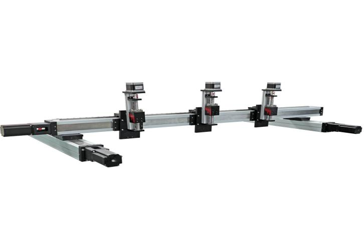
In a gantry-style multi-axis stack, pitch error from the bottom axis becomes a systematic offset for every axis mounted above it.
Here’s a real example from our assembly floor:
|
Configuration |
Measured Pitch Error over 100 mm Travel (arc-sec) |
|
Single axis, X-only |
15 |
|
2-axis stack (X + Y), worst-case compound |
38 |
|
3-axis stack (X + Y + Z), with 2 kg overhung load |
62 |
You can see the numbers don’t simply add — they compound with load and moment arms. This is exactly why pitch error troubleshooting in a multi axis linear stage must look at the whole stack, not just individual axes.
Step-by-Step Pitch Error Troubleshooting
When a customer calls us with a wobble problem, we follow a proven sequence. It works whether you have our stages or anyone else’s. Here’s the hands-on approach:
1. Measure First, Guess Never
You need a baseline. A laser interferometer is ideal, but an electronic level or autocollimator works too. Map the angular error along the full travel of each axis, mounted exactly as it sits in your machine. Write down the peak-to-valley pitch and yaw. Don’t skip this step — it stops you from chasing ghosts.
2. Check the Mounting Surface
This is the number one cause of linear stage wobble that we see in the field. If your base plate isn’t flat, you bolt a flat stage onto a curved surface, distorting the bearing raceways. Loosen the mounting bolts slightly and slide a feeler gauge under the stage. A 5-micron shim under one corner can cut pitch error in half. Use shim stock or scrape the surface flat.
3. Look at Your Load and Overhung Moment
Every stage has a rated moment load (Nm). If your payload extends far out, the leverage effect creates a pitch-down moment that the bearings fight constantly. Measure the distance from the carriage center to the center of mass of your tool. Multiply that by the weight. If this number exceeds the stage’s spec, you’ll see linear stage wobble increase under load. Fix it by adding a counterbalance or moving the load closer in.
4. Preload Adjustment
Crossed-roller stages and ball-bearing guides need proper preload to remove internal clearance. Over time, wear relaxes this preload, and the carriage starts to rock microscopically. Many stages have an adjustment screw or eccentric cam. Tighten it in tiny increments while monitoring the motor drive current (for motorized stages) or push force (for manual). You’re looking for a slight, smooth increase in drag. After adjustment, re-measure your pitch error. It should drop noticeably.
5. Clean and Inspect Raceways
Dirt kills precision. A particle the size of a human hair lodged in a bearing race can cause a sharp spike in pitch at a specific point in travel. Remove covers, wipe the rails with a lint-free cloth and solvent, and re-lubricate with the recommended grease. If the stage uses crossed rollers, check the cage isn’t binding. We’ve seen simple cleaning fix 30% of linear stage wobble issues instantly.
6. Orthogonality in the Stack
If your X and Y axes aren’t perfectly square, the Y-axis will climb or dive as X moves, which looks like a pitch error on the top axis. Use a precision square and dial indicator to verify the mounting angle between axes. Loosen bolts, tap gently into alignment, re-tighten in a star pattern. This one step often solves the mystery of varying linear stage wobble across different travel coordinates.
Here’s a troubleshooting cheat sheet for quick reference:
Good pitch error troubleshooting is 80% method and 20% tools. Follow the sequence and you’ll isolate the root cause.
|
Symptom |
Probable Cause |
Quick Fix |
|
Wobble constant across travel |
Bent base plate or uneven mounting | Shim mounting feet, check surface flatness |
|
Pitch spikes at one position |
Damaged or dirty raceway | Clean bearings, inspect for brinelling |
|
Wobble changes with speed |
Loose preload, excessive acceleration | Adjust preload, lower accel/decel |
|
Pitch grows with load |
Overhung moment exceeds rating | Add counterweight, reduce lever arm |
|
Error drifts with temperature |
Thermal expansion mismatch | Warm-up cycle, switch to steel-on-steel rails |
Crossed-roller vs. ball-bearing linear stages for wobble and pitch performancee
Sooner or later, anyone building a precision system faces a key selection question. It’s the classic Crossed-roller vs. ball-bearing linear stages for wobble and pitch performancee debate. No single answer fits all. Let’s break it down based on what we’ve measured on our own assembly benches over 9 years.
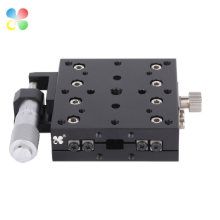
Crossed-roller stages use cylindrical rollers in a V-groove. They achieve line contact, which means higher stiffness and inherently lower angular errors. Ball-bearing linear guides use recirculating balls with point contact. They’re faster, handle longer travel easily, but have slightly lower angular stiffness.
 |
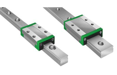 |
| Crossed-Roller Stage | Ball-Bearing Guide |
To make this concrete, here’s a comparison based on typical stages in our product range (travel 100 mm, body width 60 mm):
| Parameter | Crossed-Roller Stage | Ball-Bearing Stage |
| Typical pitch error (arc-sec) | 8 – 15 | 20 – 35 |
| Typical yaw error (arc-sec) | 10 – 18 | 22 – 40 |
| Load capacity (N) | 250 – 500 | 500 – 2000 |
| Moment stiffness (Nm/µrad) | High | Medium |
| Max velocity (mm/s) | 50 | 300 |
| Travel range (typical mm) | ≤ 300 | Unlimited (joined rails) |
| Sensitivity to contamination | High (needs bellows) | Moderate |
If your process demands the tightest possible linear stage wobble control — say in optical alignment or inspection — crossed-roller is the heavy favorite. We often steer semiconductor folks toward crossed-roller multi axis linear stage stacks for that reason. But if you need to cover half a meter of travel at high speed with a 15 kg payload and can map and compensate angular errors in software, a precision ball-bearing stage makes perfect sense.
The key is matching the technology to the real error budget, not just chasing the lowest spec on paper.
Real-World Fixes in Three Core Applications
Let’s put this into practice. Here’s how linear stage wobble and pitch errors show up — and get solved — in three demanding fields.
Semiconductor Wafer Inspection
In Semiconductor wafer inspection, a multi axis linear stage rasters a wafer under a microscope objective. Depth of focus can be less than 1 micron. If the stage stack has 30 arc-seconds of pitch, the wafer surface shifts by several microns during the scan. That gives you blurry images and missed defects.
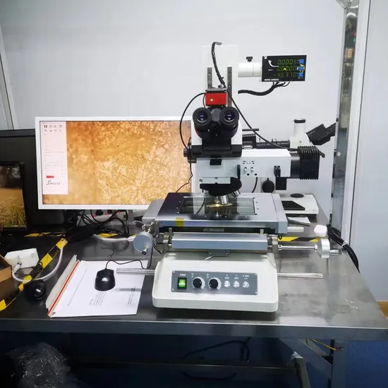
Our engineers typically attack this problem by tightening orthogonality, minimizing the Abbe offset (placing the objective right over the moving carriage), and selecting crossed-roller stages with measured pitch below 15 arc-seconds. We also recommend a warm-up cycle to stabilize thermal warping before inspection runs. One customer cut their defocus errors by 40% just by correcting the mounting base flatness.
Laser Micromachining
In laser micromachining, the beam angle matters. If the stage pitches during a cut, the kerf widens and edges get tapered. We worked with a medical device maker who was scrapping stents because of inconsistent cut quality across the work area.
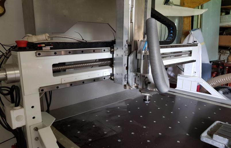
Industrial laser cutting machine with exposed linear guide rails — pitch error in the gantry axes directly translates to tapered kerfs and inconsistent cut depth across the work envelope.
Their XY multi axis linear stage had an uncorrected pitch error of 45 arc-seconds under cantilever load. By switching to a wider crossed-roller stage with a moment rating 3× higher, and using software error compensation for the residual 10 arc-seconds, they brought the cut variation within tolerance. No more scrap. The linear stage wobble issue was actually moment-induced pitch.
Automated Optical Alignment
In automated optical alignment of photonic chips, you’re trying to couple light with sub-micron accuracy. If your stage wobbles 50 arc-seconds, the coupling efficiency drops and the alignment algorithm spends time hunting.
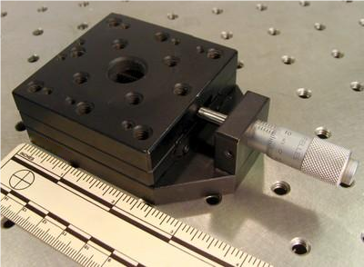
Precision manual linear stage mounted on an optical breadboard — fiber coupling and photonic alignment setups depend on sub-arc-second mechanical stability to keep the search algorithm fast and repeatable.
Our alignment platform customers typically demand single-digit arc-second wobble. They use crossed-roller multi axis linear stage assemblies with integrated piezo fine-tuning and factory-calibrated error maps. One lab we support integrated our manual crossed-roller stages with piezo actuators and achieved a 3× faster alignment cycle simply because the underlying mechanical wobble was low enough to shrink the search area.
Quick Maintenance Habits That Keep Wobble Low
Once your system is dialed in, a few simple habits prevent the wobble from creeping back:
Wipe rails every month. Use isopropyl alcohol and a lint-free wipe.
Re-lubricate on schedule. Check our manual for the right grease. Too much is as bad as too little.
Check preload every six months. We do this on our own demo units.
Re-torque mounting bolts annually. Vibration loosens them, and pitch error grows.
These steps take minutes but save hours of pitch error troubleshooting later.
When You Should Reach Out to Us
Sometimes a linear stage wobble problem runs deeper. Maybe the payload is too complex to counterbalance easily. Maybe you need a custom stage with a non-standard bearing spread. Or maybe you’re simply not sure if the error is coming from the stage or the structure.
That’s where our team can help. We’ve spent over nine years engineering manual and motorized precision stages and full alignment platforms. We don’t just sell you a part number. We talk through your load conditions, your travel sequence, your accuracy target — and recommend a multi axis linear stage setup that works from day one. Our product range covers everything from simple manual crossed-roller slides to fully automated XYZθ stacks with controller integration.
If you’re wrestling with linear stage wobble and spending too much time on pitch error troubleshooting, shoot us a message or call our application engineers. We’ve probably solved a similar challenge before, and we’re happy to share what we know.
Summing It Up
Wobble and pitch errors in multi axis linear stage systems are common, but they’re not voodoo. They come from measurable, fixable things: mounting flatness, preload, cantilever loads, bearing condition, and stack geometry. Work through a measurement-based pitch error troubleshooting sequence, pick the right guideway technology (remember the Crossed-roller vs. ball-bearing linear stages for wobble and pitch performancee trade-off), and maintain your stages with simple routines. Your process — whether Semiconductor wafer inspection, laser micromachining, or automated optical alignment — will thank you with higher yield and less downtime.
We hope this guide gives you a clear path forward. And remember, if you ever ask yourself, “How can I effectively reduce linear stage wobble and troubleshoot pitch errors in my multi-axis linear stage system?” — you’ve got a partner who’s been answering that question for nearly a decade. Let’s get your motion working exactly the way it should.
Post time: Jul-09-2026


