
Listen, if you’ve ever spent an afternoon chasing a laser spot that just won’t sit still, you already know the problem. It’s rarely the laser. It’s rarely the mirror. Nine times out of ten, it’s the thing everything is bolted to. A flimsy stage, a bit of wobble, some backlash you didn’t know was there—and suddenly your optical alignment setup becomes an exercise in frustration. We’ve been making these things for over nine years, so we’ve seen it all. Let’s walk through what actually matters when you’re picking a manual linear stage for alignment work. No fluff. Just the stuff we tell people on the phone every day.
## First Off: What’s Inside the Box?
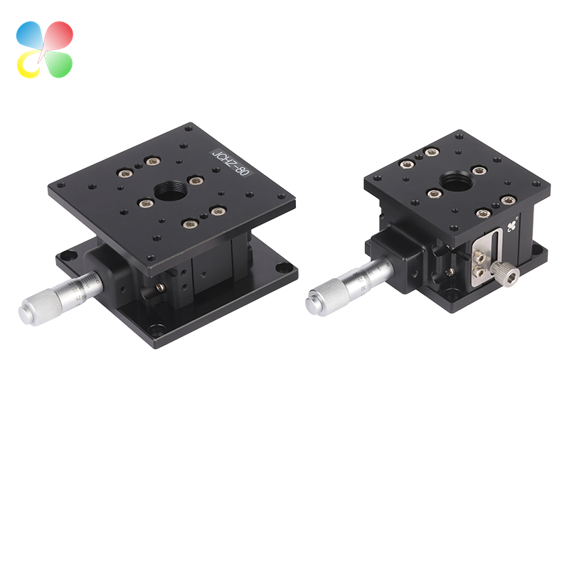
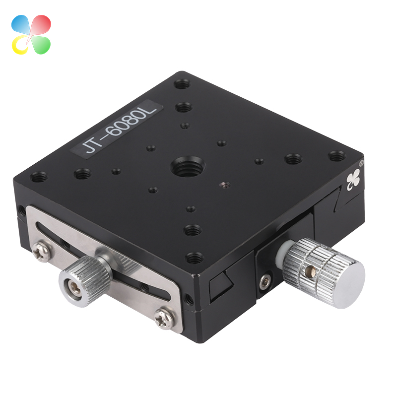
I don’t mean the shipping box. I mean that aluminum block with the shiny knob. A manual linear stage looks simple. But inside, it’s doing something quite clever.
### Yeah, But How Does a Linear Stage Work?
You might be wondering, how does a linear stage work? It’s not a silly question. Here’s the everyday version: you turn the micrometer, and that screw pushes a sled along a set of tiny rails. The trick is the thread pitch. A typical fine screw has a 0.5 mm pitch. So one full spin moves the sled forward half a millimeter. Now, that micrometer barrel usually has 50 little lines. That means one line equals 10 microns. That’s about a tenth of the thickness of a piece of paper. Your hand can’t feel 10 microns, but the stage can. And that’s how you align things by hand.
The bearings are the other half of the story. Good stages use crossed-roller bearings—little cylinders that crisscross and roll in V-grooves. They’re stiff, smooth, and they don’t wiggle sideways. If you ever feel a “clunk” when you reverse direction, that’s backlash. In a high precision optical stage, we grind and preload those bearings until backlash is under 2 microns. You won’t notice it. Your beam certainly won’t.
## The Specs You Should Sweat Over
Forget the glossy datasheets for a minute. When you’re building an optical alignment setup, five numbers actually predict whether you’ll be happy or tearing your hair out.
### 1. Travel: Be Honest with Yourself
I’ve seen orders come in for 150 mm stages when the alignment only needed maybe 15 mm. Bigger travel sounds safer, right? It’s not. Longer stage, bigger footprint, more flex, more money. Figure out the farthest your optic might need to move from its bolted-down position. Add 20% for safety. That’s your number. For 90% of fiber launch work, a 25 mm manual linear stage is plenty.
### 2. Load: It’s Not Just the Weight
The number in the catalog says “20 kg center load.” Cool. But your camera sits on a 70 mm tall pillar. That weight hanging out there creates a lever arm. It tries to twist the carriage. Our rule: if your payload is more than 40 mm above the stage surface, cut the capacity in half. That “20 kg” stage just became a 10 kg stage in the real world. Keep it centered, keep it low.
### 3. Straightness and Flatness
Straightness means the stage doesn’t wander left or right as it moves. Flatness means it doesn’t bob up and down. For image sensors or large beams, small deviations don’t kill you. For single-mode fiber coupling, they definitely can. A high precision optical stage will give you straightness below 2 µm per 25 mm of travel. That’s the kind of number that keeps a 5 µm fiber core happy.
### 4. Angular Errors: The Silent Beam Killers
Pitch, yaw, roll. Tiny angular wobbles. A 100 microradian pitch over a 100 mm lever arm moves your beam by 10 µm. For a waveguide with a 3 µm mode field, that’s a total loss. Good stages spec these below 50 µrad. The really good ones, below 20 µrad. This isn’t marketing noise—it’s geometry.
### 5. Backlash and Repeatability
Turn the knob to 8.00. Back it off. Go to 8.00 again. The difference is your uni-directional repeatability. A solid manual linear stage nails this within ±2 µm. Bi-directional repeatability—when you reverse—is tougher. That’s where backlash lives. We keep ours under 3 µm on the precision lines. If your alignment requires lots of back-and-forth tweaking, look for that number.
Here’s a down-to-earth look at the grades we actually manufacture and ship:
| What You’re Checking | Our Standard Line | Our High Precision Line | Our Ultra-Precision Line |
|---|---|---|---|
| Travel range | 6–200 mm | 13–100 mm | 6–50 mm |
| Straightness (per 25 mm) | ≤3 µm | ≤2 µm | ≤1 µm |
| Pitch / Yaw | ≤100 µrad | ≤50 µrad | ≤20 µrad |
| Backlash | ≤5 µm | ≤3 µm | ≤1.5 µm |
| Repeatability (one direction) | ±2 µm | ±1.5 µm | ±0.5 µm |
| Max center load | up to 30 kg | up to 20 kg | up to 10 kg |
| Micrometer scale | 10 µm per tick | 5 µm per tick | 2 µm per tick (differential) |
You can see the trade-off: the tighter the specs, the shorter the travel. Physics won’t budge on that. If you really need 150 mm of travel with 20 µrad pitch, we can custom-build it, but it’s not a standard part. Call us.
## The Fork in the Road: Manual vs Motorized Linear Stage
We get this question at least three times a week. Manual vs motorized linear stage—which way should you go? Let’s skip the sales pitch.
### When a Manual Linear Stage Makes You Look Smart
- You’re on a budget. A good manual unit runs $30 to $500. A motorized axis with driver is $1,000 and up, way up.
- You set it once and leave it alone. Focus the beam at 9 AM, lock the stage, run experiments all day. Done.
- You need zero electrical noise. Photodiodes with picoamp signals hate PWM motor drives.
- You work in a vacuum or cleanroom. Manual stages are way easier to prep for vacuum. Less outgassing, no cables.
- You want the feel. I’ve watched techs find peak coupling by fingertip sensitivity alone. It’s like cracking a safe. No GUI gives you that.
### When You Really Should Go Motorized
- Your alignment needs to run a grid scan or a hill-climbing optimization. Humans can’t do 500 steps by hand.
- The stage lives behind shielding or inside a glovebox where you can’t reach it.
- You need a production line to run the same motion 1,000 times a day.
- You’re synchronizing three axes at once while reading a power meter.
Here’s a side-by-side comparison that cuts to the chase:
| Manual Linear Stage | Motorized Linear Stage | |
|---|---|---|
| Budget (single axis) | $30–$500 | $1,000–$5,000+ |
| Smallest move (by hand) | 2–10 µm | |
| Repeatability (bi-dir) | ±1.5–5 µm | ±0.1–1 µm |
| Automation | None | Full script control |
| Heat generation | Zero | Motor can drift your alignment |
| Tactile feedback | Yes, direct | No, only encoder readouts |
| Upkeep | Clean & lube once a year | Cables, connectors, limit switches |
| Best home | R&D, prototyping, teaching | High-throughput, remote, scanning |
A lot of our long-time customers do a hybrid: a manual linear stage for coarse X-Y and a tiny piezo stage on top for fine Z. Best of both worlds, without the full motorized price tag.
## Building an Optical Alignment Setup That Stays Put
An optical alignment setup is only as stable as its weakest joint. I once saw a lab with a $3,000 stage bolted to a hollow breadboard with plastic feet. Every time the air conditioning kicked on, the whole thing shifted by 5 µm. Here’s what keeps things where you left them.
Solid base, no excuses. A thick aluminum plate or a honeycomb table. Vibration at 50–100 Hz loves to rattle tall post holders. Damp it.
Stack wisely. When you bolt an X stage on top of a Y stage, the bottom stage now carries the payload plus the mass of the upper stage. That bottom stage’s load rating better be high enough. People forget this all the time.
Keep the stack short. Tall stacks amplify angular errors like crazy. If you must have 120 mm of height, use a solid riser block under a combined XY stage, not three single-axis units piled up. We build rigid XY ganged stages exactly for that.
Lock it down gently. Standard locks can shift the carriage by 2–5 µm when you tighten them. Our high precision optical stage locks nudge it less than 1 µm. After you lock, check your signal again. If you know the shift amount and direction, you can compensate. It’s a feel thing, but you’ll get it.
Warm it up. Aluminum grows about 23 µm per meter per degree C. Steel grows half that. If your stage is aluminum and your optic holder is steel, a 2°C swing in the lab can give you a few microns of drift. Let everything sit for 30–40 minutes after you turn the room lights on, then do your final tweak.
## Not Just for Optics: Linear Stage for Laser Marking
We sell a ton of stages that never see a laser beam in an alignment sense. A common one is using a linear stage for laser marking. Let’s say you’re marking engine valves with a 50 W fiber laser. The beam is fixed. The part needs to sit at exactly the right focus height. You can use a manual linear stage for that Z height adjustment. Travel of 100–120 mm, load capacity 20 kg, 10 µm resolution. The operator sets the height for a batch, locks it, and runs. It’s fast, it’s cheap, and it just works. When marking curved parts, you might even shift Z by a millimeter between runs. Again, manual, simple, reliable.
Other places you’ll spot our stages:
- Test labs: scanning a probe across a circuit board.
- Machine vision: setting back focal distance on a line-scan camera.
- Biomedical rigs: positioning flow cells.
- Inspection stations: moving dies under a microscope.
- Assembly jigs: placing tiny parts before bonding.
Each one comes back to the same checklist: travel, load, and stiffness. The rest is details.
## Pick the Right Stage Without the Headache: A Checklist
Our application engineers use a seven-question routine. Steal it.
1. What axis do I need? X? Y? Z? Tilt? Most optical work needs at least X-Y-Z plus maybe tip/tilt.
2. How much travel? Measure the farthest distance from loose mount to tightest. Add 15–20%. Be ruthless.
3. How heavy is the payload? Weigh everything—optic, holder, adapter, cable strain. Multiply by 1.5 for safety. Cut capacity in half if the load hangs far out.
4. What resolution really matters? For single-mode fiber (mode ~5 µm), you want a high precision optical stage with straightness ≤2 µm/25 mm and backlash under 3 µm. For free-space beams with a 1 mm detector, standard grade is fine.
5. Micrometer type? Standard 0.5 mm pitch, 10 µm ticks. Differential screw if you need that silky sub-micron feel.
6. Environment? Vacuum? Cleanroom? High vibration? Tell us upfront. We do vacuum prep and clean greases.
7. Locks and stops? Hard stops protect the stage from over-travel. Low-shift locks keep your alignment intact.
A quick crib sheet for the most common tasks:
| What You’re Doing | Suggested Travel | Load | Precision Grade | Extra Advice |
|---|---|---|---|---|
| Fiber launch alignment | 13–25 mm (X,Y,Z) | <3 kg | Ultra-Precision | Differential micrometer, low stack |
| Steering a free-space beam | 25–50 mm | <5 kg | High Precision | Rigid mounts, lock stages after set |
| Camera focus and centration | 25–50 mm (Z) | <10 kg | High Precision | Center-load as much as possible |
| Microscope sample scanning | 50–150 mm (X,Y) | <15 kg | Standard–High | Flatness is key here |
| Focus height for laser marking | 50–120 mm (Z) | <30 kg | Standard | Industrial environment, easy locking |
| Waveguide alignment | 6–13 mm (X,Y,Z) | <2 kg | Ultra-Precision | Pair with a piezo fine stage if needed |
## Mistakes That Make Us Wince
After nine years, we’ve seen the same blunders on repeat.
- Chasing the cheapest stage. That $120 import says 10 µm accuracy. By the time it drifts 25 µm with a temperature change, you’ve lost half a day. A proper high precision optical stage comes with an inspection report. Insist on it.
- Ignoring stiffness. A stage with great specs but a thin, flexible base will bend under load. Ask for a stiffness number. Our 60 mm wide stage has a frame rigidity around 50 N/µm. It matters.
- Using the micrometer as a clamp. Don’t crank it past the stop. You’ll brinell the threads and add backlash. Use the lock screw to hold position, not the adjustment knob.
- Mixing metric and inch parts. A 25 mm stage with a 1/2″ adapter sounds close. It isn’t. The tolerance stack creates tilt. Pick one system.
- Forgetting cables. A stiff fiber or a heavy BNC cable pulls on your carriage. It can shift your alignment by several microns. Strain relief is not optional in a serious optical alignment setup.
## Let’s Be Honest: We Want You to Call Us
We’re not just here to sell you a part number. We make these things in-house. That means we can tweak the travel, the mounting hole pattern, the vacuum grease, the micrometer orientation—whatever makes your life easier. Lead times are usually 2 to 4 weeks. Custom mods have shipped in 10 days when you’re in a pinch.
If your setup involves aligning something sensitive, or if you’re torn between manual vs motorized linear stage, let’s talk. A 15-minute call can save you weeks of trial and error. We’ll help you pick the right manual linear stage, the right linear stage for laser marking height adjustments, or a full XYZ stack for your optical alignment setup.
Drop us an email with your sketch, a photo of your bench, or even just a napkin drawing. We’ll get you a recommendation and a CAD model within a business day. And if you need a batch of 50 units for a production floor, we do that too.
Ready to stop chasing microns? Reach out.
[Insert your contact email / form]
Prefer a call? [Insert phone]
We ship worldwide, and we stick with you long after the sale.
Choosing a manual linear stage doesn’t have to feel like a gamble. Nail the specs, talk to someone who builds them, and you’ll have an optical alignment setup that stays true all day. We’re ready when you are.
Post time: Jun-26-2026


