

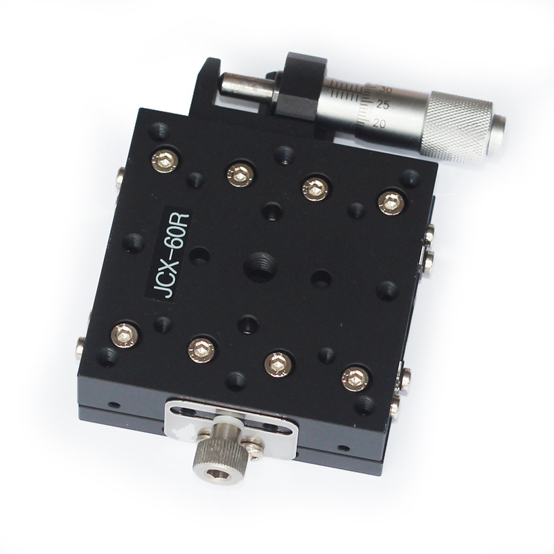
We’ve been making manual and motorized stages for over 9 years. We’ve talked to a lot of buyers. Most of them start with travel range and price. That’s normal. But then they run into a problem. The stage moves smoothly. The numbers look fine. Yet the alignment still won’t hold.
Nine times out of ten, the issue is not X, Y, or Z. It’s pitch, roll, and yaw.
A tiny angular error can kill your result. It doesn’t matter how fine the screw is. It doesn’t matter how smooth the slide feels. If the platform tilts or twists, your target moves. And the farther away your target is, the worse it gets.
This blog is for buyers and engineers who want straight answers. We’ll keep it simple. We’ll use real numbers. We’ll also show you where a manual alignment stage fits, when a 3 axis manual positioning stage is enough, and when you need an angular displacement stage.
Angle Errors Grow With Distance
Let’s start with the one thing many buyers miss.
A small angle error does not stay small. It turns into a big linear error as distance increases.
The formula is simple:
Linear error = angle in radians × distance
Here’s a quick table. These numbers are real. You can use them during selection.
| Angular error | At 100 mm | At 200 mm | At 300 mm | At 500 mm |
| 0.01° | 17.5 µm | 34.9 µm | 52.4 µm | 87.3 µm |
| 0.05° | 87.3 µm | 174.5 µm | 261.8 µm | 436.3 µm |
| 0.1° | 174.5 µm | 349.1 µm | 523.6 µm | 872.7 µm |
| 0.5° | 872.7 µm | 1,745 µm | 2,618 µm | 4,363 µm |
| 1° | 1,745 µm | 3,491 µm | 5,236 µm | 8,727 µm |
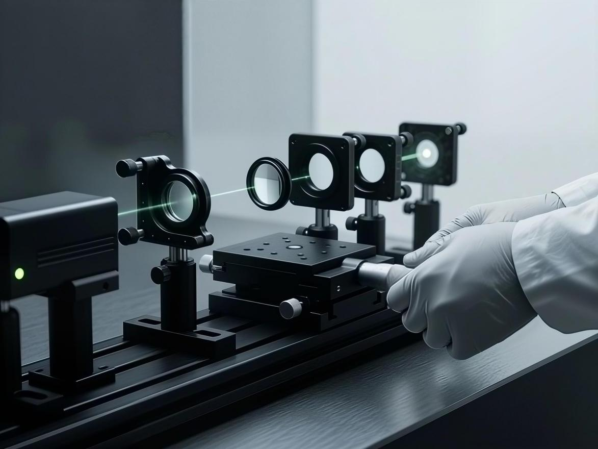
Now think about your own job. If you’re aligning a fiber at 200 mm, and your stage has 0.1° of yaw, you’re off by about 349 µm. For single-mode fiber, that’s huge. The core is only about 9 µm. You’ll never get good coupling.
That’s why a manual alignment stage is not just about linear travel. It’s about controlling the angles too.
How Do Pitch, Roll, and Yaw Affect the Accuracy of a Manual Alignment Stage?
This is the question we hear a lot. Let’s break it down without fancy language.
Pitch, roll, and yaw are just three ways a stage can rotate when you don’t want it to.
|
Motion |
What it does |
What you see |
|
Pitch |
Nose up or down |
Beam moves up/down at target |
|
Roll |
Tips left or right |
Beam moves left/right at target |
|
Yaw |
Turns flat left or right |
Beam shifts sideways or rotates |
|
Theta |
Rotation around Z |
Component angle changes |
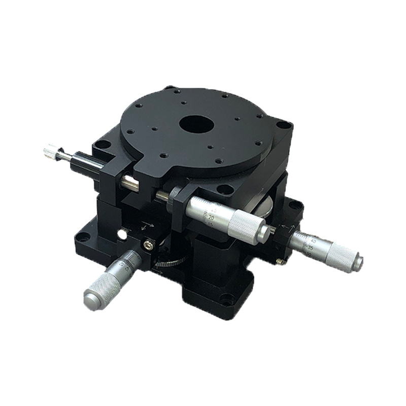
On a manual alignment stage, these errors come from many places. Bearings. Screws. Flatness. Assembly. Load. Locking. Temperature. Even the operator.
Pitch usually hurts height. Roll usually hurts side position. Yaw is often the worst for optics. It can rotate a lens, prism, or mirror. That changes the beam path. It can also create cross-coupling. You adjust X. Then Y. Then you notice the tilt is off. You fix tilt. Now X and Y are off again. That back-and-forth wastes time.
We’ve seen this in real projects. A customer bought a cheap 3-axis stage. It had good linear resolution. But the yaw error was over 0.2°. At 300 mm, that’s more than 1 mm of side shift. They spent two days trying to align a simple laser setup. In the end, they added an angular displacement stage. Problem solved in an hour.
What Causes Angular Error in Real Stages
You can’t fix what you don’t understand. Here are the common causes we see.
1. Flatness error.
If the top plate isn’t flat, the load tilts. A 10 µm flatness error over 100 mm can create about 20 arcseconds of tilt. That’s enough to matter.
2. Bearing clearance.
Ball bearings and dovetail slides have clearance. Too much clearance means the platform rocks. That shows up as pitch and roll.
3. Screw and nut alignment.
A lead screw or micrometer head can push the stage at a slight angle. That creates yaw. A poor nut adds backlash and stick-slip.
4. Assembly error.
Good parts can be assembled badly. If rails aren’t parallel, the stage binds. If the top plate isn’t seated, the load tilts.
5. Off-center load.
A 5 kg load placed 50 mm off-center creates a moment. That moment bends the stage or compresses one side. Pitch and roll get worse.
6. Locking shift.
Many manual stages use a clamp or set screw to lock. If the lock pushes the platform, your alignment moves. A good lock holds without shifting.
7. Temperature change.
Aluminum expands about 23 µm per meter per °C. Steel is about 11 to 13 µm. A 2°C change on a 200 mm aluminum stage can move a point by about 9 µm. Over time, that’s drift.
8. Operator force.
Manual stages depend on the operator. Push too hard, and you flex the stage. Turn too fast, and you overshoot. Training matters.
|
Error source |
Typical angular effect |
How to reduce it |
|
Flatness error |
5 to 50 arcsec |
Specify flatness, use lapped surfaces |
|
Bearing clearance |
10 to 100 arcsec |
Use preloaded bearings |
|
Screw misalignment |
5 to 30 arcsec |
Use fine screws, align nuts |
|
Off-center load |
10 to 200 arcsec |
Center load, increase stiffness |
|
Locking shift |
5 to 50 arcsec |
Use low-shift locks |
|
Thermal drift |
1 to 20 arcsec per °C |
Low-CTE material, stable room |
|
Operator force |
10 to 100 arcsec |
Use knobs, train operators |
3 Axis Manual Positioning vs. Angular Displacement Stage
Now let’s compare two common choices. This is where buyers often get stuck.
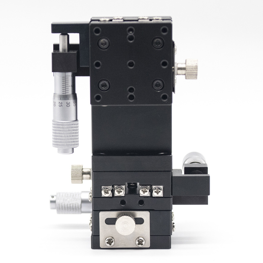
A 3 axis manual positioning stage gives you X, Y, and Z linear movement. It’s great for moving a sample or tool in space. It’s simple. It’s affordable. It works well for inspection, probe stations, and basic fixtures.
An angular displacement stage controls rotation. It may handle pitch, roll, yaw, or theta. Some call it a tip/tilt stage. Some call it a rotation stage. It’s used when the angle of a part matters as much as its position.
| Feature | 3 Axis Manual Positioning | Angular Displacement Stage |
| Main motion | X, Y, Z linear | Pitch, roll, yaw, theta |
| Best for | Moving a part to a location | Setting tilt or rotation |
| Typical resolution | 1 µm to 10 µm | 1 arcsec to 1 arcmin |
| Common use | Probe, fixture, simple optics | Laser, fiber, camera, prism |
| Cross-coupling risk | Medium to high if poorly made | Lower with good design |
| Price | Lower | Medium to high |
| Learning curve | Easy | Moderate |
| Load capacity | Often higher | Often lower |
So which one do you need? It depends on your error budget.
If your target is large and the distance is short, a 3 axis manual positioning stage may be enough. If your target is small and the distance is long, you need angular control. In many real jobs, you need both. Use the 3-axis stage for coarse placement. Then use an angular displacement stage for final tilt and rotation.
Don’t ask, “Which is better?” Ask, “Where does my error come from?” If it comes from tilt, buy tilt control. If it comes from position, buy linear control.
Optical Component Alignment with a Manual Alignment Stage
Let’s look at a real application: Optical Component Alignment with a Manual Alignment Stage.
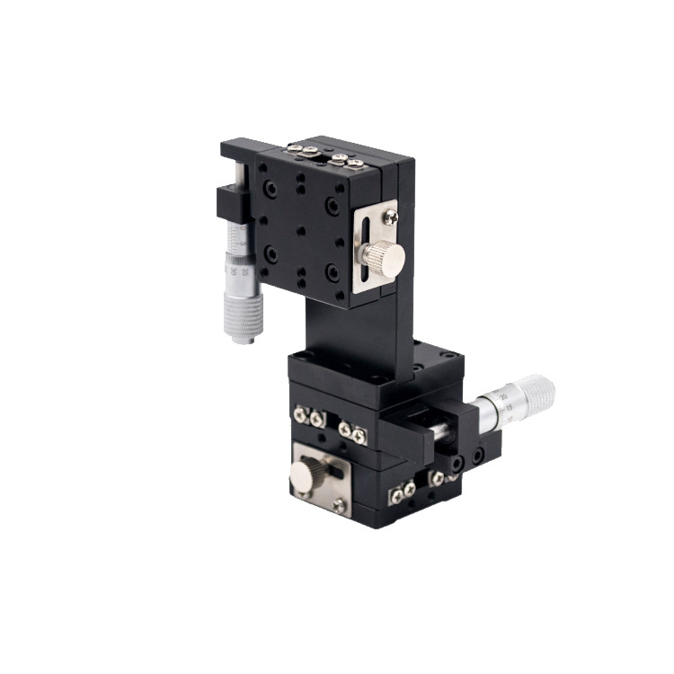
Optical work is unforgiving. A lens, mirror, fiber, or camera sensor must be in the right place and at the right angle. A few microns off, and the signal drops. A small angle off, and the beam walks away.
Here are some common tasks and what they need.
|
Application |
Linear tolerance |
Angular tolerance |
Recommended setup |
|
Single-mode fiber coupling |
< 1 µm to 5 µm |
< 0.01° |
5-axis or 6-axis manual alignment stage |
|
Laser diode to lens |
5 µm to 20 µm |
< 0.05° |
3 axis manual positioning + tip/tilt |
|
Camera module focus |
10 µm to 50 µm |
< 0.1° |
3 axis manual positioning + rotation |
|
Prism alignment |
20 µm to 100 µm |
< 0.02° |
Angular displacement stage + linear stage |
|
Mirror mount alignment |
50 µm to 200 µm |
< 0.01° |
Tip/tilt stage with fine screws |
|
Fiber array alignment |
1 µm to 10 µm |
< 0.02° |
Multi-axis manual alignment stage |
Notice something? Angular tolerance is often tighter than linear tolerance. That’s not a mistake. In optics, angle errors grow with distance. A 0.01° error at 500 mm is about 87 µm. That can be the difference between strong signal and no signal.
For optical work, a good manual alignment stage should have fine pitch screws, low backlash, high stiffness, good thermal stability, and a lock that doesn’t shift the platform. If the stage has loose bearings or soft metal, you’ll fight it all day.
A Simple Buyer Example
Let’s say you need to align a laser beam to a detector. The detector is 300 mm away. The beam must stay within 50 µm. You also need to adjust lens tilt. Your budget is moderate. You want manual, not motorized.
|
Requirement |
Value |
What it means |
|
Working distance |
300 mm |
Angle errors grow with distance |
|
Linear tolerance |
50 µm |
Need fine X, Y, Z |
|
Angular tolerance |
0.01° |
About 36 arcsec total |
|
Load |
1 kg |
Light load |
|
Adjustment axes |
X, Y, Z, tip, tilt |
5 axes total |
|
Locking |
Must not shift |
Low-shift lock needed |
For this job, a simple 3 axis manual positioning stage may not be enough. You need angular control. A better choice is a 3-axis stage plus a tip/tilt angular displacement stage. If budget allows, a 5-axis manual alignment stage saves space and reduces cross-coupling.
|
Option |
Pros |
Cons |
Best for |
|
3 axis manual positioning only |
Low cost, simple |
No tilt control |
Large targets, short distance |
|
3 axis + tip/tilt |
Good balance |
More setup time |
Most optical alignment |
|
5-axis manual alignment stage |
Compact, less cross-coupling |
Higher cost |
Fiber, laser, camera |
|
6-axis manual alignment stage |
Full control |
Most expensive |
Complex optics, R&D |
|
Angular displacement stage only |
Best for tilt |
No linear travel |
Prism, mirror, rotation |
Specs That Matter More Than Marketing
When you compare stages, don’t just read the first page. Look for real numbers.
|
Specification |
Why it matters |
Good sign |
Warning sign |
|
Travel range |
Fits your adjustment |
Clear X, Y, Z travel |
Vague “large travel” |
|
Resolution |
Smallest step |
1 µm or better linear |
“High resolution” only |
|
Repeatability |
Return to same spot |
< 2 µm |
Not listed |
|
Angular resolution |
Smallest tilt step |
< 10 arcsec |
Not listed |
|
Backlash |
Lost motion |
< 2 µm |
“Low backlash” only |
|
Straightness |
Devates from line |
< 3 µm per 25 mm |
Not listed |
|
Flatness |
Top stays flat |
< 5 µm |
Not listed |
|
Stiffness |
Holds under load |
Test data |
No load curves |
|
Load capacity |
Will it sag? |
5 kg, 10 kg, or more |
No number |
|
Locking |
Does it shift? |
Low-shift design |
Simple set screw |
A good supplier gives you numbers. A great supplier helps you test them in your application.
Quick Tips to Reduce Pitch, Roll, and Yaw
You can buy a good stage and still get bad results. How you use it matters.
Shorten the working distance if you can. At 100 mm, a 0.1° error is 175 µm. At 500 mm, it’s 873 µm.
Use the right stage for the right axis. Don’t fix an angle problem with a linear stage.
Align coarse to fine. Large moves first. Fine screws last.
Center the load. Off-center weight causes pitch and roll.
Lock one axis at a time. Check position after each lock.
Control temperature. A 2°C change can move a 200 mm aluminum stage by about 9 µm.
Measure correctly. Use an autocollimator or electronic level for angles.
Train the operator. Light force. Same direction every time.
Questions to Ask Your Supplier
Before you buy a manual alignment stage, ask these.
What is the angular resolution in arcseconds?
What is the repeatability after locking?
How much does the stage shift when locked?
What is the straightness and flatness?
What is the load capacity at center and off-center?
What material is used? What is the thermal expansion?
Can you provide a test report for pitch, roll, and yaw?
Do you offer custom mounting patterns?
What is the lead time for a 3 axis manual positioning stage?
Can you help me choose between a 3-axis stage and an angular displacement stage?
If the supplier can’t answer these, keep looking. You’re not buying a commodity. You’re buying alignment performance.
How We Can Help
We have over 9 years of experience in manual and motorized stages. We make manual alignment stages, 3 axis manual positioning platforms, angular displacement stages, and automated alignment platforms. We focus on R&D, production, and sales.
If you’re working on optics, fiber alignment, camera modules, or precision fixtures, we can help. Tell us your working distance, target tolerance, load, and adjustment axes. We’ll recommend the right stage. We can also do custom designs, drawings, samples, and OEM support.
Contact us through our website or email our sales team. Let’s find the right manual alignment stage for your project. Don’t wait until you’ve wasted days on alignment. Send your requirements today.
Final Word
Pitch, roll, and yaw are not academic terms. They are real sources of error. A tiny angle can create a big miss. A 0.1° error at 300 mm is about 524 µm. A 10 arcsec error at 200 mm is about 9.7 µm. The difference matters.
When you choose a stage, look at the full picture. Linear travel is important. Angular performance is just as important. Repeatability, stiffness, locking, and thermal stability all play a role.
If you need 3 axis manual positioning, check whether you also need an angular displacement stage. If you’re doing Optical Component Alignment with a Manual Alignment Stage, pay extra attention to pitch and yaw. They are often the hidden reason alignment takes too long.
We’re here to help. With 9+ years of experience, we can guide you from selection to production. Contact us today and tell us what you need to align. We’ll help you get it right the first time.
Post time: Oct-09-2026


