

If you work with optics, assembly lines, or lab setups, you already know the feeling. You nudge a knob by a hair. The stage moves just enough. The alignment locks in. That kind of control doesn’t come from luck. It comes from the micrometer head sitting at the end of your manual stage. Over the last 9 years, we’ve built, tested, and shipped thousands of positioning systems. One thing never changes: the micrometer is the soul of a high resolution manual stage. Choose the right one, and your manual micro positioning becomes effortless. Choose the wrong one, and you’ll fight with drift, backlash, and coarse steps all day.
This guide digs into what matters. We’ll compare standard and differential heads, walk through a real fiber alignment use case, and explain how the right micrometer linear stage directly shapes your repeatability numbers. By the end, you’ll know exactly what to look for—and when to call us.
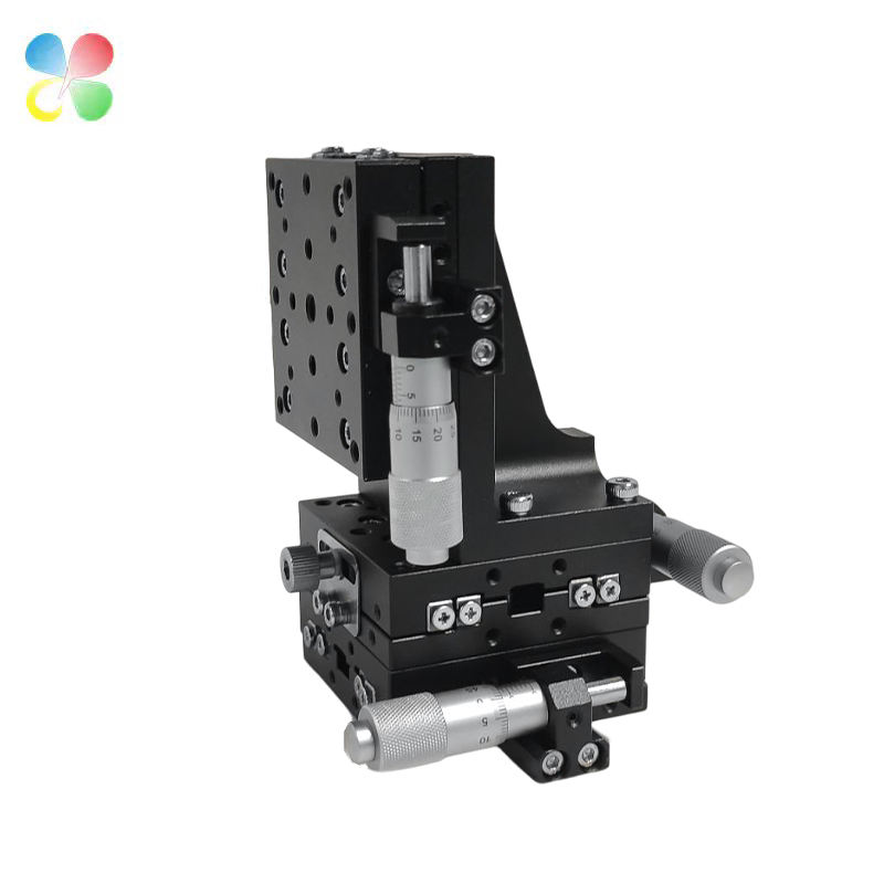
Figure 1: A multi-axis manual linear stage with precision micrometer heads — the core interface between your fingertips and sub-micron positioning.
Why the Micrometer Head Defines Your Manual Micro Positioning
The body of a manual stage matters. Parallelism, material, cross-roller bearings—all important. But your hands never touch those. What you feel is the micrometer. It turns your rotation into a linear push. That push moves the carriage. A stage with an excellent bearing structure but a poor micrometer will still feel gritty. It will overshoot. It will drift back after you let go.
Here’s a simple way to think about it:
● Resolution = smallest movement you can consistently make.
● Repeatability = ability to return to the same position after multiple moves.
● Feel = smoothness and feedback under your fingertips.
All three are heavily influenced by the micrometer head. A high resolution manual stage typically uses a finer thread pitch or a differential mechanism inside the micrometer. A standard stage might use a 0.5 mm pitch thread and a 10 μm graduation drum. That gives you 10 μm per division. In many labs, that’s fine. But in fields like photonics, the gap between 10 μm and 1 μm is huge. That’s when you need to think about stepping up.
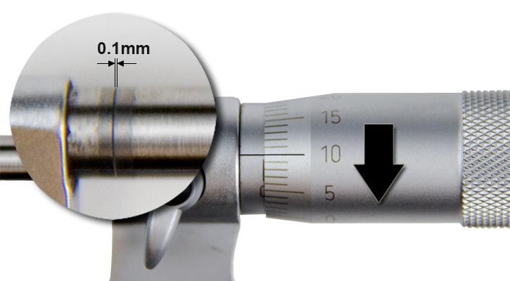
Figure 2: Micrometer thimble with fine graduation markings — each division represents the smallest incremental motion you can reliably command.
We often tell customers: if you can feel the clicks of the micrometer, you can control the movement. If you can’t, you’re just guessing.
How can a high resolution manual stage with a micrometer linear stage improve your manual micro positioning repeatability?
This question hits the core of what many engineers worry about. The answer sits in three places: thread quality, drum resolution, and friction control.
When you turn a micrometer thimble on a micrometer linear stage, the spindle pushes the stage carriage. The finer the screw thread, the smaller the linear movement per degree of rotation. A typical standard head has a pitch of 0.5 mm. One full rotation (360°) advances the spindle by 0.5 mm. If the thimble has 50 divisions, each line equals 10 μm. That’s your theoretical resolution. But real repeatability is rarely that perfect. Backlash, stick-slip, and thermal effects eat into it.
Now consider a high resolution manual stage equipped with a differential micrometer or a fine-pitch standard head. A differential micrometer can have an effective pitch as fine as 0.025 mm or even 0.01 mm per revolution. With 50 divisions on the drum, you might get 0.5 μm or 1 μm per division. At that level, your manual micro positioning repeatability improves dramatically—often from ±5 μm down to ±0.3 μm.
Here’s why. Coarse threads have more clearance between the male and female threads. That clearance creates axial play. When you reverse direction, the spindle travels a bit before engaging again. That’s backlash. A fine-pitch or differential micrometer minimizes that dead zone. Less dead zone, better bidirectional repeatability. You can nudge back and forth without losing position.
Friction control is the silent player. Cheaper micrometer heads sometimes use a simple spring-loaded nut to reduce backlash. Works initially. But over hundreds of cycles, wear loosens it. Better heads use precision-lapped threads with controlled preload. The movement stays smooth and consistent. No jump. No drift after lock. Our experience across 9 years of building these stages confirms: the difference in repeatability between a $30 micrometer and a $200 differential head isn’t just on paper. It’s in how many times you need to re-align.
So, the answer to the question: a high resolution manual stage that pairs an accurate, low-backlash micrometer linear stage gives you finer control, smaller dead band, and thermal stability. This directly tightens your manual micro positioning repeatability from “close enough” to “exactly where you left it.”
Standard vs. Differential Micrometer for High Resolution Manual Stages
When you’re building or buying a manual positioning system, you’ll face this exact comparison. Let’s break it down without marketing fluff.
A standard micrometer head is what most people imagine. A thimble, a graduated scale, a spindle. It’s simple, affordable, and widely available. For many industrial inspection setups or coarse pre-alignments, it’s more than enough. We supply dozens of these every month for customers who need reliable 10 μm steps.
A differential micrometer takes a completely different approach. It uses two concentric screws with slightly different pitches. The outer thimble moves a coarse nut, and the fine thimble adjusts a second differential nut. The net movement is the difference between the two pitches. So if one screw moves 0.5 mm per rev and the other 0.475 mm, the relative motion per rev is only 0.025 mm. That’s 20 times finer. You get sub-micron resolution without a motor, without complex gearboxes. Just pure mechanical advantage.
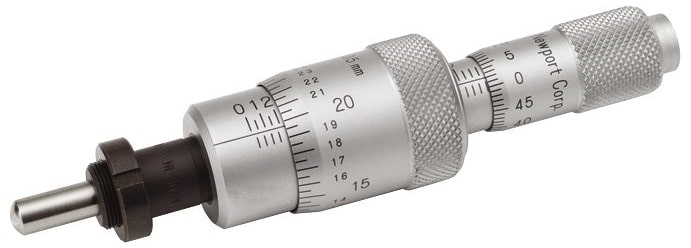
Figure 3: A differential micrometer head featuring dual concentric thimbles — the two nested screws create an effective pitch far finer than either screw alone.
But there are trade-offs. The table below shows what we’ve measured in our own assembly and testing of both types used in manual micro positioning applications.
|
Feature |
Standard Micrometer |
Differential Micrometer |
|
Typical graduation |
10 μm (0.01 mm) | 1 μm or 0.5 μm (0.001–0.0005 mm) |
|
Travel per revolution |
0.5 mm | 0.025–0.05 mm |
|
Sensitivity (practical) |
5–10 μm | 0.3–1 μm |
|
Bidirectional repeatability |
±2–5 μm | ±0.3–0.5 μm |
|
Axial load capacity |
Higher | Lower (due to fine mechanism) |
|
Durability in harsh environments |
Very good | Needs protection from dust |
|
Cost |
$30–$80 | $150–$400+ |
|
Best suited for |
General alignment, training, inspection | Fiber optic alignment, waveguide coupling, laser cavity tuning |
|
Feel |
Slightly coarser but robust | Silky fine, very low backlash |
Looking at the numbers, you can see the pattern. A standard micrometer linear stage works great for applications where 5 μm is a comfortable margin. A high resolution manual stage built around a differential micrometer becomes a precision tool for sub-micron manual micro positioning. The selection is not about “better” in an absolute sense. It’s about what your process demands. We usually ask customers three questions: What’s your smallest target alignment tolerance? How often do you reverse direction during adjustment? Is your environment dusty or clean? Based on that, we recommend one over the other. If you’re undecided, contact us directly. We ship sample spec sheets with real measured performance, not just catalog numbers.
Real-World Need: Fiber Optic Alignment High Resolution Manual Stage
Let’s put these comparisons into a concrete scenario. Few applications push a manual stage harder than single-mode fiber alignment. The core diameter of a single-mode fiber is around 8–10 μm. You need to align two fiber cores to within a fraction of that to maximize coupling efficiency. A misalignment of just 1 μm can drop your power coupling by several percent. That’s the domain of a Fiber Optic Alignment High Resolution Manual Stage.
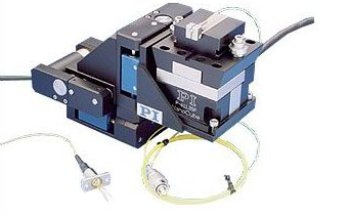
Figure 4(example): Multi-axis fiber alignment stage system — sub-micron resolution is essential when coupling single-mode fibers with 8–10 μm cores.
In these setups, you typically need multiple axes: X, Y, and Z, plus sometimes pitch and yaw. Each axis must move with sub-micron resolution and return to the same spot after repeated cycles. No one trusts a coarse stage here. You need a high resolution manual stage with very fine pitch screws or differential heads. The micrometer linear stage becomes the steering wheel for light. Our customers often use a combination: a coarse micrometer linear stage for initial positioning, then lock it and fine-tune with a differential micrometer on the same platform. The result is a workable manual micro positioning solution that can hit 0.5 μm repeatability without piezo actuators.
Here’s a typical sequence in a fiber launch test:
1. Place fibers on holders mounted to the manual stages.
2. Use a coarse 10 μm resolution micrometer linear stage to bring the fiber tips within roughly 20–30 μm.
3. Switch to the differential-driven axis on a Fiber Optic Alignment High Resolution Manual Stage.
4. Slowly optimize X, Y, Z while watching the power meter.
5. Lock the micrometers. Measure coupling. Then cycle the stage away and back to check repeatability.
We’ve seen setups where a manual micro positioning approach with high-quality heads achieves coupling efficiency repeatability within 0.2 dB cycle-to-cycle. That’s comparable to some motorized systems but at a fraction of the cost and complexity.
If you deal with silicon photonics, waveguide probing, or laser diode coupling, you know this dance. The most common frustration is drifting after lock. That’s almost always due to internal micrometer thread relaxation or insufficient stiffness in the stage carriage. That’s exactly why we preload our micrometer mounts and use dual-rail cross-roller guides. The extra rigidity keeps a high resolution manual stage dead still after lock. Our application engineers can help you map out the required travel, resolution, and load capacity for your specific fiber array or V-groove assembly. Just reach out.
What to Look for When Specifying a Manual Micro Positioning Stage
With so many options on the market, it helps to have a checklist. Over 9 years of manufacturing, we’ve identified a handful of specs that actually affect your day-to-day work. When you talk to a supplier—whether it’s us or someone else—ask for these numbers.
1. True Resolution vs. Catalog Resolution
Catalog resolution often assumes perfect conditions and no load. Ask for the practical resolution—the minimum incremental motion you can reliably command. For a standard micrometer linear stage, that’s usually 10 μm. For a differential stage, 0.5 μm or better.
2. Backlash and Hysteresis
This matters if you approach a target from different directions. Always ask for bidirectional repeatability. A manual micro positioning stage with 2 μm backlash might sound fine, but in fiber alignment it will show up as a consistent offset. We measure backlash on every stage and include it in the test sheet.
3. Straightness and Flatness of Travel
The micrometer moves a carriage. If that carriage wobbles or pitches, you get Abbe errors. A high resolution manual stage with poor guidance can have 10 μm of angular deviation, completely spoiling the fine micrometer resolution. Look for cross-roller or linear ball bearing designs with specification under 2 μm runout.
4. Thermal Stability
Your hand transfers heat to the micrometer body. Over a few minutes, thermal expansion can shift the position by a few microns. This is especially important when you’re doing lengthy alignments with a Fiber Optic Alignment High Resolution Manual Stage. We use stainless steel spindles and low-expansion materials to keep drift below 1 μm over typical cycle times.
5. Locking Mechanism
A simple side lock screw can tilt the spindle and shift the position by several microns when tightened. That’s a huge no for precision manual micro positioning. Better stages use split-sleeve clamps or rear locks that don’t introduce lateral forces. We’ll be happy to explain the difference; ask for our technical note on locking drift.
If any of these points raise a question about your current setup, don’t hesitate to get in touch. We help engineers upgrade their existing stages with better micrometer heads, often saving them the cost of a complete new stage.
Building a System: Integrating Micrometer Linear Stages into Your Setup
An individual micrometer linear stage is just one piece. Real systems use stacked stages or multi-axis platforms. One thing we learned early: the stack height and adapter plates can degrade precision. Every interface adds tolerances. If you stack an X stage and a Y stage with loose bolt holes, you’ll lose repeatability right at the mechanical interface. We machine our mounting surfaces flat and square within a few microns. Our assembly technicians torque bolts in a sequence to minimize stress.
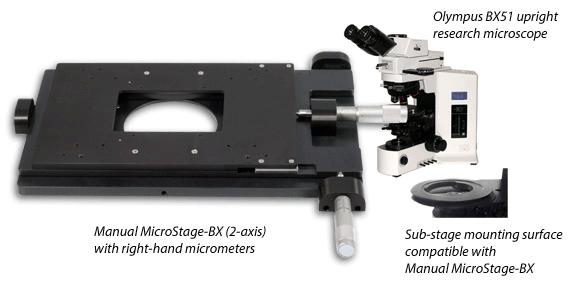
Figure 5: Integrated XY manual micro-positioning stage — machined mounting surfaces and sequenced bolt torqueing minimize stack-up error between axes.
For a multi-axis high resolution manual stage assembly, consider this approach:
● Use the same micrometer type across axes for consistency of feel.
● Align the micrometer tip squarely against the drive pad to avoid side loading.
● Preload the stage slightly beyond your normal load to settle the bearings.
● Run a warm-up cycle: 10 full strokes before critical alignment. This distributes lubrication and stabilizes temperature.
We provide a short installation guide with each shipment. But honestly, a 10-minute call with our support team can shorten your integration time significantly. You get the benefit of 9 years of problem-solving, and you won’t have to re-discover common pitfalls.
Why 9 Years of Stage Manufacturing Experience Matters
We’ve been making manual and motorized precision stages since 2015. In that time, we’ve seen fads come and go, and we’ve seen what truly holds up in real production floors. Cheap micrometer heads wear out. Plastic drums fade. Lock screws drift. These are things you only learn after thousands of units in the field. Today, we source our micrometer components from specialized machining partners who meet our tolerances—thread roundness within 0.001 mm, drum marking accuracy verified by laser. For high resolution manual stage platforms, we assemble and test each unit under a laser interferometer. You get the actual performance data, not just generic promises.
Our catalog covers full-range manual micro positioning solutions: from 13 mm travel single-axis micrometer linear stage units to 6-axis alignment platforms for photonics packaging. We keep standard models in stock and can customize travel, mounting patterns, or vacuum-compatible versions. If you’re not sure which configuration suits your application, email or call us. We’ll put together a quick sketch and spec proposal at no charge.
Quick Decision Table for Choosing Your Micrometer Linear Stage
Use this table when you’re comparing options. It’s based on what our customers typically need.
|
Your Application Requirement |
Recommended Stage Type |
Expected Repeatability |
|
Coarse alignment, training, visual inspection |
Standard micrometer linear stage, 10 μm graduation | ±5 μm |
|
Optical power meter alignment, multimode fiber |
Standard fine-pitch stage, 5 μm graduation | ±2 μm |
|
Single-mode fiber coupling, waveguide alignment |
Differential high resolution manual stage | ±0.5 μm |
|
Semiconductor die pick-and-place training |
Standard stage with lock, robust build | ±3 μm |
|
Laser cavity mirror tuning |
Differential manual micro positioning stage with vacuum compatibility | ±0.3 μm |
|
Repeated cycling in cleanroom environment |
Differential Fiber Optic Alignment High Resolution Manual Stage | <0.5 μm drift per cycle |
This table is a starting point. Your exact requirements might involve speed, load, or footprint. We can send you a detailed selection guide if you drop us a message.
A Few More Words on Manual Micro Positioning Technique
Even the best high resolution manual stage won’t mask poor technique. Here are a few hands-on tips we share during customer training sessions:
● Always approach the target from the same direction. It cancels backlash.
● Don’t rest your full hand on the micrometer; use finger and thumb lightly. Body heat transfers fast.
● Give the stage 5–10 minutes after power-on (if motorized) or after handling to thermally stabilize.
● Clean the micrometer spindle tip and the drive pad regularly with isopropyl alcohol. Dust particles can act like tiny springs.
● When locking, watch the position readout. If it jumps, your lock mechanism is pushing the stage. We can suggest retrofit locks.
These small habits can squeeze an extra 0.5–1 μm of repeatability out of your manual micro positioning setup. It’s what separates a good operator from a great one.
Let’s Talk About Your Next Project
If you’re reading this, you probably have a positioning challenge on your desk right now. Maybe your current stage drifts after lunch. Maybe you’re building a new test rig and need a Fiber Optic Alignment High Resolution Manual Stage that won’t ruin your yield. We’d love to hear about it.
Here’s what you get when you work with us:
● 9 years of expertise in manual and motorized stages.
● Direct manufacturer pricing—we design, machine, and assemble in-house.
● Actual interferometer test reports with every high resolution manual stage.
● Fast customization: custom mounting patterns, travels, and vacuum options.
● Post-sale support from engineers who build the stages.
We’ve already helped labs integrate manual micro positioning systems for quantum optics, silicon photonics, laser processing, and biomedical device alignment. No project is too small. The knowledge we’ve built around micrometer linear stage performance is yours for a conversation.
Drop us an email, call our offices, or fill out the quick inquiry form on our website. Tell us your required travel, load, and target resolution. We’ll recommend a stage or custom solution that fits your budget and technical needs. Whether you need a single standard micrometer linear stage or a multi-axis differential high resolution manual stage, we’ll make sure you get the precision you expect.
Let’s maximize your precision together.
Post time: Jul-29-2026


