

When inspection systems get faster, every millisecond counts. A slow rotary axis can throttle your entire automated inspection positioning line. Over the years, we’ve talked to hundreds of engineers who struggle with exactly that. They need speed. They need precision. And they need both in a compact, reliable package. That’s where a well-designed motorized rotation stage makes all the difference.
In this post, I’ll share what we’ve learned from nine years of building manual stages, motorized stages, and alignment platforms. You’ll get real numbers, a clear side-by-side table, and tips you can use right away. We’ll also dive into the common question:
How to choose a high-speed motorized rotation stage for automated inspection positioning?
Let’s walk through it step by step.
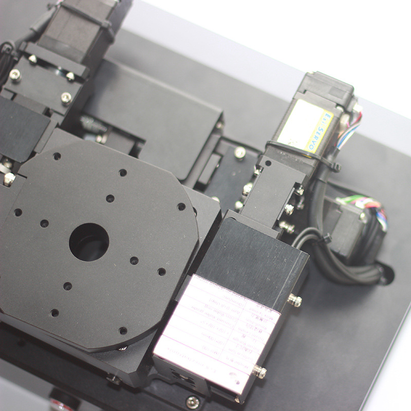
Why Speed Defines Modern Automated Inspection Positioning
Automated optical inspection (AOI), X-ray inspection, and laser scanning systems share one thing. They need the part to be in the right place — fast. If your rotary axis takes 2 seconds to settle after each move, you lose hundreds of inspection cycles per shift. Over a month, that’s thousands of lost parts.
An high speed rotary stage slashes that settle time. Some of our direct-drive units can hit a top speed of 500 rpm. More importantly, they stop on a dime. In semiconductor wafer inspection, a 300mm wafer might need four or five angle stops in under a second. A slow worm-gear stage simply can’t keep up. The result? Inspection becomes the bottleneck.
When engineers think about automated inspection positioning, they usually look at the XY table first. But the rotary axis is just as critical. It handles the angular position. If it wobbles, the entire field of view shifts. If it creeps, the defect coordinates go haywire. In high-throughput lines, a solid motorized rotation stage is not optional; it’s a requirement.
Understanding the Motorized Rotation Stage Basics
Let’s keep this simple. A motorized rotation stage is a precision device that rotates a load around a single axis, driven by a motor. You mount your part, fixture, or chuck on top. You send a command. The stage moves to a set angle.
The core parts usually include:
A base and a rotating table.
Bearings (cross-roller, angular contact, or air bearings).
A drive mechanism.
A motor (stepper, servo, or direct-drive torque motor).
An encoder or feedback system.
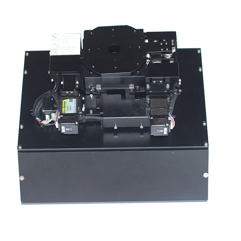
The difference between a good motorized rotation stage and a great one shows up in the details: runout, wobble, repeatability, and thermal stability. In high-speed applications, these details get magnified. A tiny bearing clearance becomes a visible wobble at 300 rpm.
Direct Drive vs. Worm Gear Rotary Stage — Real Numbers That Matter
This is one of the most common choices engineers face. I’ll break it down with a straightforward comparison. The table below lists typical values we’ve measured from units we’ve built and tested. Your actual numbers may vary depending on size and load, but the trend is consistent.
Post time: Aug-12-2026


