

If you build automation equipment, lab instruments, or production machinery, you have probably hit the same wall many times. You find a nice manual stage online. The travel looks right. The load rating is okay. But the mounting holes don’t match your fixture. Or the stage is 12 mm too wide. Or you need a different drive knob because your operator wears gloves.
That is exactly why custom manual stages exist. They are not just for huge aerospace projects. They are for everyday OEM buyers who need a stage that fits their machine, their process, and their budget. We have spent more than 9 years making manual and motorized positioning stages, plus precision alignment platforms. Most of our work involves some level of customization. In this guide, I will walk you through a practical blueprint for ordering a custom manual stage, from first spec to final batch.
What should OEM buyers evaluate when choosing a custom manual stage from an OEM positioning stage manufacturer for high-precision linear slider integration? That is the central question. Let’s answer it piece by piece.
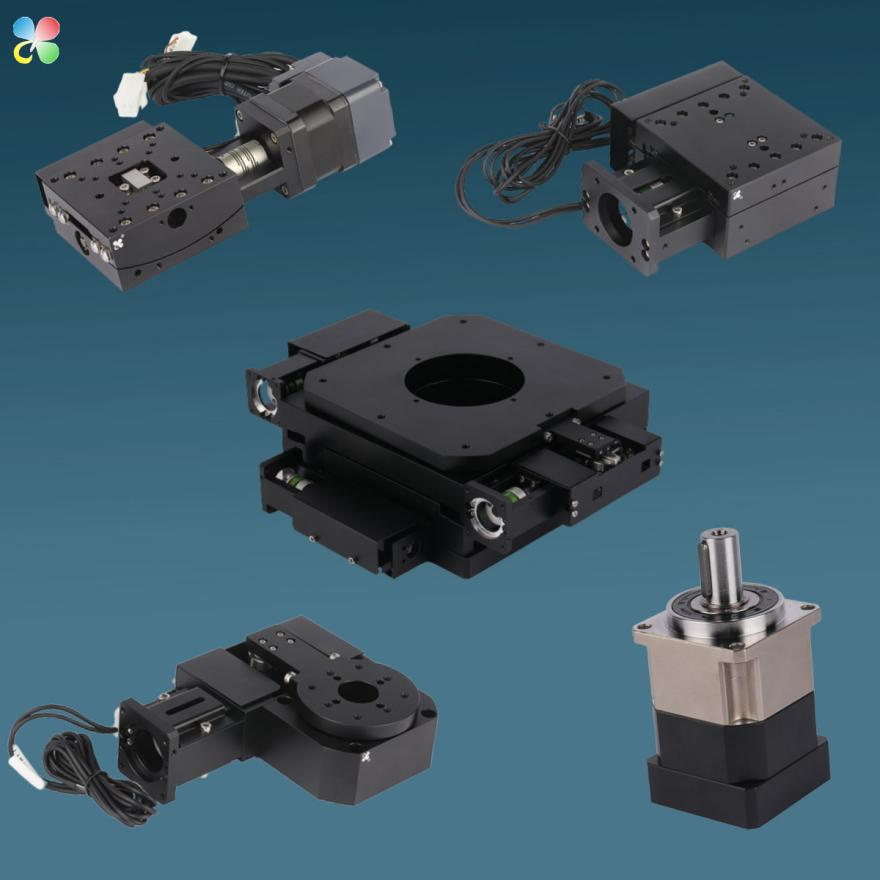
Start With the Real Requirements, Not a Wish List
The first step sounds simple. Write down what the stage must do. But many buyers skip this and jump straight to a catalog. Then they end up with a stage that is too big, too heavy, or too expensive. When you contact an OEM positioning stage manufacturer, be ready to answer four things:
How far does the stage need to travel? (stroke)
How much weight sits on the stage? (load)
What level of smoothness or precision do you need? (guide type)
How will you mount the stage and the payload? (hole pattern)
If you only know the first two, that’s fine. A good manufacturer will help you figure out the rest. But don’t leave the details until the end. They change the design.
Travel Range vs. Load Capacity: The First Big Trade-Off
Once you know your basic needs, you will face the most common comparison in stage selection. Travel range vs. load capacity. These two specs pull against each other in many designs. A long travel stage usually has a longer base and more guide surface. That can handle more load, but it also adds size and cost. A short travel stage is compact, but its load capacity drops, especially if the load hangs off the edge.
Let’s look at a table we often share with OEM customers. It shows typical combinations and where they fit in real applications.
|
Travel Range |
Center Load Capacity |
Typical Application |
Recommended Guide Type |
|
25 mm |
5–10 kg |
Sensor alignment, fiber optic adjustment |
Crossed roller, compact body |
|
50 mm |
10–20 kg |
Laser marking, optical inspection |
Crossed roller, standard body |
|
75 mm |
15–30 kg |
Dispensing heads, camera focus |
Crossed roller or ball bearing |
|
100 mm |
20–40 kg |
Wafer inspection, PCB drilling |
Crossed roller, wide body |
|
150 mm |
30–60 kg |
Semiconductor wafer alignment, probe stations |
Crossed roller, heavy-duty base |
|
200 mm |
50–80 kg |
Gantry alignment, assembly fixtures |
V-groove or dual rail |
|
300 mm |
80–120 kg |
Large format automation, screen printing |
Dual linear rails with machined base |
These numbers are not set in stone. They depend on guide preload, material, and how the load is distributed. But the table gives you a realistic starting point. If your load is off-center, reduce the capacity by 30–50%. If you use a vertical mounting orientation, reduce it further. Always mention orientation when requesting a quote.
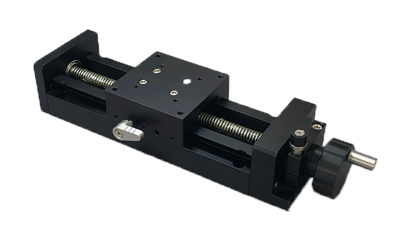
Why Standard Stages Fail in Semiconductor Wafer Alignment
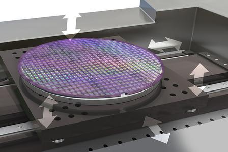
One application we see all the time is semiconductor wafer alignment. This process demands very smooth motion, tight flatness, and a small footprint. A standard manual stage often fails for three reasons.
First, the mounting holes. Wafer chucks and vacuum platens have very specific hole patterns. You can’t just drill new holes into a hard anodized aluminum stage without risking cracks or misalignment. A custom top plate solves this cleanly.
Second, the drive sensitivity. In wafer alignment, a small turn of the knob should move the stage only a few microns. Standard micrometer heads with 0.5 mm pitch work well. But a cheap stage with a 2 mm pitch screw makes fine adjustment nearly impossible. We recommend a fine-pitch lead screw or a micrometer drive for any wafer-related task.
Third, the environment. Many wafer processes happen in cleanrooms or near chemicals. Standard black anodized aluminum may shed particles or corrode over time. Electroless nickel plating or stainless steel hardware is a safer choice. We have built dozens of custom manual stages for wafer alignment with these upgrades. The difference in performance is immediate.
A real example: a customer needed a 100 mm travel stage for a wafer chuck that weighed 11 kg. The stage had to be less than 90 mm wide. Standard stages were either too wide or too short. We used a crossed roller guide, a fine-pitch screw with 0.5 mm per revolution, and a custom top plate with M4 holes matching their chuck. We also added a side locking clamp that did not shift the position when engaged. The customer ordered 50 units for their first production run.
How an OEM Positioning Stage Manufacturer Handles Custom Orders
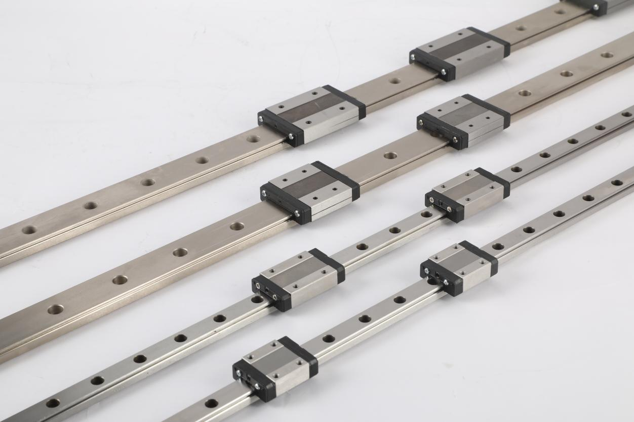
Now let’s talk about the process. Working with a custom stage manufacturer should not feel like pulling teeth. We follow a simple four-step method that keeps things moving.
Step 1: Spec review. You send us a drawing, a napkin sketch, or even a photo of your current setup. We don’t need perfect CAD. We just need travel, load, and any space limits. Our engineers review it and ask questions within 24 hours.
Step 2: Proposal and drawing. Within 2–3 business days, we send a 2D layout drawing and a firm quote. The drawing shows all critical dimensions, drive type, and mounting holes. This is your chance to catch any mismatches before we cut metal.
Step 3: Prototype or first article. For new designs, we always recommend one sample first. You test fit, smoothness, and repeatability. If something needs a tweak, we adjust the drawing. Once you approve, we lock the design.
Step 4: Batch production. We manufacture the approved design in your required quantity. Typical lead time for a custom manual stage batch is 3–4 weeks, depending on volume and finishing. We provide a dimensional inspection report with every shipment.
We have used this process for over 9 years. It removes guesswork and keeps surprises to a minimum. When you work with an OEM positioning stage manufacturer, the goal is not just a one-time sale. The goal is a design you can reorder for years without headaches.
Custom Linear Slider Wholesale: What Changes at Scale
Many OEM buyers start with a few prototypes, then scale to monthly or quarterly batches. That’s where custom linear slider wholesale becomes important. Buying in larger quantities changes the conversation in a few ways.
First, price. Unit cost drops as quantity rises. For a typical custom manual stage, ordering 50 pieces instead of 5 can reduce unit price by 20–30%. Ordering 200 pieces can reduce it by 35–40%. The exact savings depend on material, finishing, and assembly time.
Second, consistency. At volume, you can’t afford variation between batches. We use dedicated fixtures and jigs for repeat orders. That means hole positions, flatness, and drive feel stay the same from batch one to batch ten.
Third, packaging and labeling. Do you need each stage individually boxed with your part number? Do you want them bulk-packed in trays? We handle both. Some customers ask for a cleanroom wipe-down before packaging. That’s possible too.
Here is a quick reference for wholesale planning:
|
Order Quantity |
Typical Unit Price Change |
Recommended Actions |
|
1–10 pieces |
Baseline |
Use standard drawing, expect 2–4 week lead |
|
10–50 pieces |
5–10% lower |
Review for common hardware, combine setups |
|
50–200 pieces |
10–15% lower |
Dedicated fixtures, safety stock options |
|
200+ pieces |
15–20% lower |
Annual contract, monthly releases, JIT delivery |
We don’t ask for a huge upfront payment. For established OEM relationships, we can set up a 30% deposit and 70% before shipment, or even open payment terms for long-term partners. Talk to us about your volume. We will find a plan that works.
Three Mistakes to Avoid When Specifying a Custom Manual Stage
Over the years, we have seen a few errors pop up again and again. They cause delays, extra costs, or field failures. Here are the big three.
1. Forgetting the Locking Mechanism
A manual stage moves when you turn the knob. But it also needs to stay put when you let go. Many standard stages use a simple friction lock. That’s fine for lab use, but in a machine with vibration, it can drift. If your process needs stable positioning, ask for a positive lock. A split clamp or a lead screw with a self-locking pitch works better. In semiconductor wafer alignment, even a tiny drift can ruin a batch. Don’t skip this detail.
2. Ignoring Environmental Factors
Aluminum stages with black anodizing are great for clean, dry rooms. But if your stage sits near coolant, solvents, or high humidity, that anodized layer can wear or stain. Stainless steel hardware is a minimum. Electroless nickel plating on the base adds corrosion resistance. For vacuum or cleanroom use, we can use special lubricants that don’t outgas. Tell us where the stage will live. It changes the material list.
3. Underestimating Lead Time for Custom Parts
A custom manual stage is not a stock item. It takes time to machine, finish, assemble, and inspect. If you need 20 pieces in two weeks, we will try, but rush fees may apply. Plan for 3–4 weeks on new custom orders. For repeat orders with existing tooling, we can often cut that to 2 weeks. The earlier you contact us, the smoother the schedule.
Our Most Requested Custom Configurations
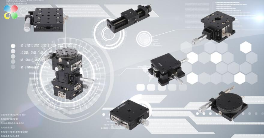
To make this concrete, here are three configurations we build frequently for OEM buyers. They are not off-the-shelf products. They are platforms we modify to your exact needs.
Configuration A: Compact Crossed Roller Stage
Travel: 25–50 mm
Load capacity: up to 15 kg center load
Drive: Micrometer head with 0.5 mm pitch or fine screw
Lock: Side clamp
Body material: Black anodized aluminum
Guide: Crossed roller with cag
Typical use: Sensor positioning, optical fiber alignment, small camera focus
Configuration B: Medium-Duty Linear Stage with Quick Lock
Travel: 50–150 mm
Load capacity: up to 40 kg center load
Drive: Lead screw with 1 mm pitch or micrometer head
Lock: Top-mounted thumb screw
Body material: Electroless nickel plated steel or aluminum
Guide: Crossed roller or ball bearing
Typical use: Laser marking, dispensing heads, PCB routing, inspection stations
Configuration C: Heavy-Duty Wide Stage for Automation
Travel: 100–300 mm
Load capacity: up to 120 kg center load
Drive: Worm gear or fine pitch screw with 0.25 mm per revolution
Lock: Dual side clamps
Body material: Stress-relieved aluminum or steel
Guide: Dual linear rails or V-groove bearings
Typical use: Assembly automation, gantry integration, large fixture positioning
All of these can be customized with a different top plate size, special hole patterns, vacuum compatibility, or cleanroom lubrication. You don’t have to start from a blank sheet. We already have the core platforms. Your job is to tell us what to change.
Why Buyers Stick With Us for the Long Haul
We could list our 9 years of experience or our full range of manual and motorized stages. But what matters more is how we handle the details. When you send a drawing, we don’t just quote it. We check every dimension. If a tolerance seems too tight for the material, we say so. If a hole position will collide with a guide rail, we flag it. That level of review saves you from costly mistakes.
One customer told us they had tried three other suppliers before us. The stages they received never matched the drawing exactly. With us, the first sample fit on the first try. That didn’t happen by luck. It happened because we asked about their full assembly, not just the stage.
Another customer needed a custom linear slider wholesale order of 300 stages per year for a medical device assembly line. We worked with them to standardize three travel lengths using the same base design. That cut their inventory cost and made their service team happier. Small design choices like that make a big difference over time.
The Simple Way to Get Started
If you are tired of forcing standard stages into your design, let’s talk. The process is easy. You send us an email or fill out the contact form. Include your travel range, your load, and any space constraints. A photo or rough sketch helps. We will review it and get back to you within one business day.
For urgent projects, we can usually provide a 2D layout within 48 hours. Prototypes can ship in 2–3 weeks depending on complexity. Batch orders follow your production schedule.
Don’t let a standard stage limit your design. A custom manual stage from a reliable OEM positioning stage manufacturer is not a luxury. It is a practical way to make your machine work better, look cleaner, and last longer. Whether you need a single sample or a custom linear slider wholesale program, we are ready to help.
Contact us now to discuss your custom manual stage requirements. Let’s build the right motion solution together.
Post time: Aug-26-2026


