

Multi-Axis Motorized Gantry Systems: Design Rules for Large Formats
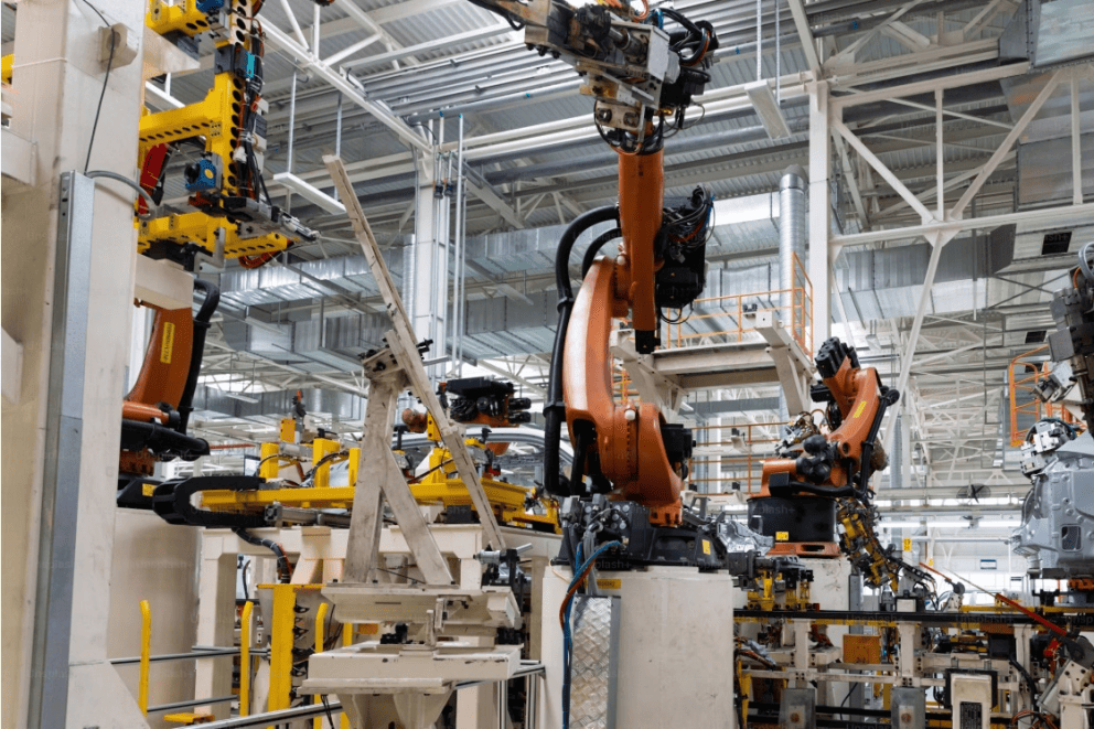
Ever tried to move a heavy inspection head across a 3-meter glass panel and hold a few microns of accuracy? You quickly realize that off-the-shelf stages just don’t cut it. At that scale, you need a motorized gantry system that is designed from the ground up for stiffness, repeatability, and long-term reliability.
In this post, we want to share those rules. We’ll answer a question we hear almost every week. We’ll compare drive choices in detail. And we’ll look at one real application that ties everything together: Automated Optical Inspection (AOI) of Large Glass Substrates. Stick around – there’s a handy comparison table and a few download-worthy tips you can use right away.
What Are the Critical Design Rules to Build a Motorized Gantry System into a High-Precision Multi-Axis Automated Stage for Extreme Large Travel Positioning Tasks?
That question is long, but it captures exactly what engineers like you ask us. Let’s unpack it rule by rule. Each rule comes from mistakes we’ve seen – and fixed – in the field.
Rule 1 – Start with the Base, Not the Actuator
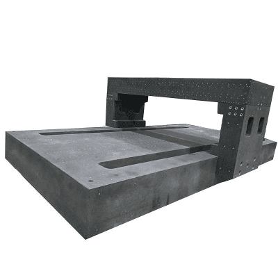
When someone asks for a large travel positioning stage, they often start by talking about motors and encoders. We start by talking about granite, steel weldments, and vibration.
Over a 1.5 m or 2 m travel, the flatness of the mounting surface directly eats into your straightness budget. For a motorized gantry system traveling 2 meters, we recommend the base plate flatness to be held within 0.05 mm over the entire length. If you mount a precision linear guide on a surface that bows 0.2 mm, no feedback system will fully recover the lost accuracy.
What works in practice:
- Use a stress-relieved steel base or a granite surface plate for large spans.
- Mount the gantry uprights on a common rigid subframe, not on separate floor stands.
- Run a modal analysis early. Your first resonance should be above 50 Hz under full payload.
Rule 2 – Match the Drive to Your Real Duty Cycle
Drive selection makes or breaks the performance of a multi-axis automated stage. This brings us directly to the big comparison.
Belt Drive vs. Direct Drive for Multi-Axis Automated Stages
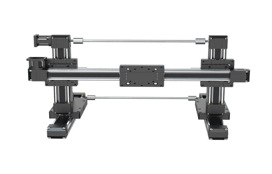
We see a lot of confusion here. Let’s clear it up with data, not marketing talk. Below is a table based on our own integration results and customer feedback over almost a decade.
|
Parameter |
Belt Drive Gantry |
Direct Drive (Linear Motor) Gantry |
| Typical repeatability | ±10 µm to ±50 µm | ±0.5 µm to ±3 µm |
| Max velocity | 1.5 – 2.5 m/s | 2 – 5 m/s |
| Max acceleration | 0.5 – 1.5 g | 2 – 5 g |
| Position stability | Some settling time; backdriving possible | Very stiff, no mechanical windup |
| Maintenance | Belt tension checks, periodic replacement | No mechanical wear, only guide and cable carrier |
| Cost (relative) | 1x | 2.5x – 4x |
| Travel limit (per axis) | Easily extends beyond 5 m | Typically up to 3-4 m for practical magnet tracks |
| Best for | Lower duty cycle, budget-sensitive AOI, dispensing | High-speed pick-and-place, semiconductor metrology, long-run production |
In our experience, if your large travel positioning stage sees fewer than 500 cycles per day and you can tolerate ±20 µm, a well-tuned belt drive with a quality gearbox saves a lot of money. But if you need to inspect every millimeter of a large glass substrate at 300 mm/s with sub-5-µm precision, you will want a direct drive motorized gantry system. The absence of belt stretch and backlash makes the control loop much tighter.
One practical tip: for belts, never spec the width below 25 mm on travels over 1 m. We have seen 15 mm belts introduce oscillation that no tuning can fix.
Rule 3 – Synchronize Multiple Axes Correctly
A multi-axis automated stage is not just two single-axis stages bolted together. On a large gantry, the two X-axis motors (master and slave) must stay locked to within a few encoder counts. Any skew and the cross-axis (Y) will bind, or your tool tip will yaw.
We always use one of these methods:
- Electronic gearing with a real-time controller: the slave follows the master at microsecond rates.
- Cross-coupled control with dual linear encoders: both sides report to the motion controller, and errors are corrected directly.
For a large travel positioning stage over 2 m, we add a precision crossbar to tie the two X axes mechanically. This passive stiffness helps the control loop. We target a crossbar rigidity such that the vertical deflection under 20 kg load is less than 15 µm. This simple rule eliminates many geometry headaches.
Rule 4 – Choose the Right Feedback for the Job
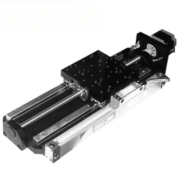
Never rely only on a rotary encoder on the motor. For a motorized gantry system meant for metrology or AOI, you need direct linear feedback.
- For belt drives: a linear encoder on the load, with resolution 0.5 µm or better.
- For direct drives: an absolute or incremental linear encoder with reference marks; analog sine/cosine signals if you need sub-micron interpolation.
We recommend adding a secondary scale on the slave side to monitor cross-axis twist. When you are building a multi-axis automated stage for 10 µm accuracy over 1 m, this simple add-on can detect thermal drift in real time.
Rule 5 – Manage Cables and Hoses Like They Are Part of the Structure
A cable carrier that snags can tilt a precision axis by 20 µm. We have measured it. For a large travel positioning stage, use a generously sized cable carrier with partitioned chambers to separate power and signal lines. Route air and vacuum hoses inside. Secure the bending radius to no less than 10 times the cable diameter. The drag force should stay under 5 N over the whole travel. Test this with a force gauge before final assembly – it takes 10 minutes and saves hours of debugging.
Rule 6 – Control Temperature and Vibration at the Start
A change of 1 °C can make a steel gantry beam grow by about 12 µm per meter. For a 2-meter motorized gantry system, that’s 24 µm. If your spec is ±5 µm, you are already in trouble without knowing it.
Practical things we do:
- Place the gantry on vibration isolation pads if the floor has forklift traffic.
- Use symmetric structure to minimize differential expansion.
- Switch on the system 30 minutes before running high-precision jobs, and keep the environment within ±1 °C.
Real-World Application: Automated Optical Inspection (AOI) of Large Glass Substrates
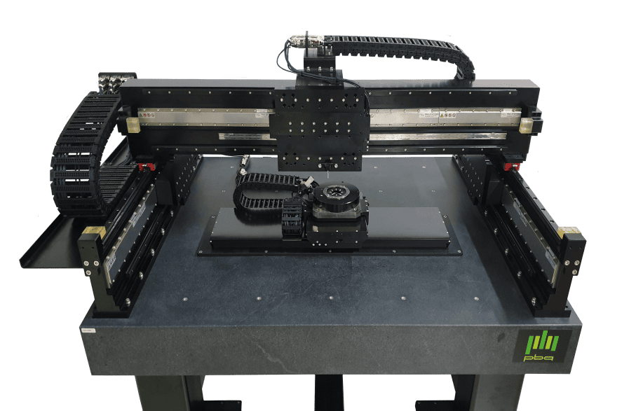
Let’s see how these rules apply in a real case. This customers, a flat panel display inspection company, needed a large travel positioning stage for Automated Optical Inspection (AOI) of Large Glass Substrates. The substrate size was Generation 8.5 (2,200 mm × 2,500 mm). The requirement: scan the full panel with a 5x line-scan camera and hold a pixel resolution of 2 µm, while moving at 250 mm/s.
Challenges we faced:
- Travel: 2,700 mm in X, 2,500 mm in Y.
- Payload: a 40 kg optical head with camera, lens, and autofocus.
- Flatness requirement: vertical runout under 10 µm across the entire scan area.
- Base: We used a massive granite base with a passive air isolation system. The gantry frame was aluminum with steel linear guide rails bolted every 150 mm to maintain straightness.
- Drive selection: We chose a direct drive multi-axis automated stage for both X axes and the Y cross axis. This eliminated belt backlash and allowed synchronized velocity ripple under 0.5%.
- Synchronization: The dual X motors ran with cross-coupled control referencing two 1 nm resolution linear scales. The Y axis used a single linear motor with a stiff bridge beam weighing only 16 kg – low moving mass kept acceleration high without sacrificing stiffness.
- Thermal control: The enclosure maintained ±0.5 °C. We used non-contact temperature sensors on the granite to compensate residual drift in software.
Here’s how we applied the design rules:
The result: the motorized gantry system achieved a bidirectional repeatability of ±1.5 µm over the full 2,700 mm travel, and the AOI scan maps showed zero stitch artifacts. The machine has been running two shifts a day for over two years. That’s what a design-rules-first approach delivers.
Quick Decision Matrix: Belt or Direct Drive for Your Gantry?
If you are still unsure which path to take, use this simple checklist we give our customers.
|
Your Application Profile |
Our Recommendation |
|
Large panel AOI, speed <300 mm/s, budget tight |
Belt drive with linear encoder and rigid crossbar |
|
High-speed dispensing over 1.2 m x 1.5 m |
Belt drive, dual motor synchronization |
|
Semiconductor wafer metrology, <2 µm accuracy |
Direct drive, granite base, active vibration control |
|
Laser micromachining of PCB, acceleration >2 g |
Direct drive, lightweight cross axis |
|
Gen 10.5 glass inspection, 24/7 operation |
Direct drive, temperature-managed enclosure |
|
University lab setup, frequently reconfigured |
Belt drive modular gantry, with easy tension adjustment |
Remember: a large travel positioning stage is always a system, never just a component. The interface between the base, the drives, and the metrology is where precision is born or lost.
Common Mistakes We See (And How to Avoid Them)
1. Specifying travel too tight.
Always add at least 50 mm extra travel on each end. For a multi-axis automated stage, overtravel margins prevent accidental hard stops and give room for end-effector offsets.
2. Ignoring cable mass.
On a 3-meter axis, the cable carrier and cables can weigh over 5 kg. That mass moves and shifts the center of gravity. Include it in your inertia calculations.
3. Choosing the lightest frame to save cost.
A light frame deflects more. An extra 5 kg of aluminum in the right place can raise the resonant frequency by 20%. That’s the difference between stable scanning and blurry images.
4. Setting encoder resolution without looking at the whole signal chain.
A 1 nm linear scale means nothing if your analog signal has 200 mV of noise. We always perform a noise floor test with the motor powered and the stage stationary. Aim for a peak-to-peak noise under 3 encoder counts.
How We Can Help You
With over 9 years of building manual and motorized stages, we have seen a wide range of large travel positioning stage requirements. We design and assemble complete motorized gantry system solutions in-house, including custom bridge beams, multi-axis controllers, and machine vision integration. Our focus is on multi-axis automated stage platforms that balance accuracy, speed, and cost.
What you can expect when you work with us:
- A technical consultation call to review your payload, travel, duty cycle, and environment.
- 3D CAD concepts showing the proposed gantry layout and integrated cable management.
- A test report for every stage we deliver, documenting repeatability, straightness, and flatness data.
- Support for on-site installation and tuning if needed.
If you are evaluating a large travel positioning stage for an upcoming project, let’s talk before you finalize the spec. Small changes early can save months of rework and tens of thousands of dollars.
Let’s Start a Conversation
Whether your process is AOI, laser scribing, dispensing, or advanced metrology, a well-designed motorized gantry system is the backbone of your throughput and yield. We enjoy diving into tricky requirements – the kind where standard catalogs fall short.
Ready to discuss your application?
- Tell us your travel, payload, and accuracy goal.
- Share a sketch or a CAD step file.
- We’ll come back with a feasibility note and a ballpark within 48 hours.
Visit our [Contact Us] page or email our application team directly. Your next multi-axis automated stage could be running on the shop floor faster than you think.
We hope these design rules help you build a better, more reliable gantry. If you found this post useful, share it with a colleague who is speccing a large travel automation system. And if you have a specific design challenge, reach out. After more than 9 years in this field, we have likely solved something similar before.
Post time: Jul-16-2026


